
Introduction: new board, new console!
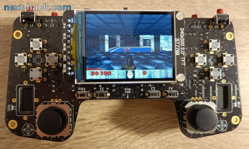
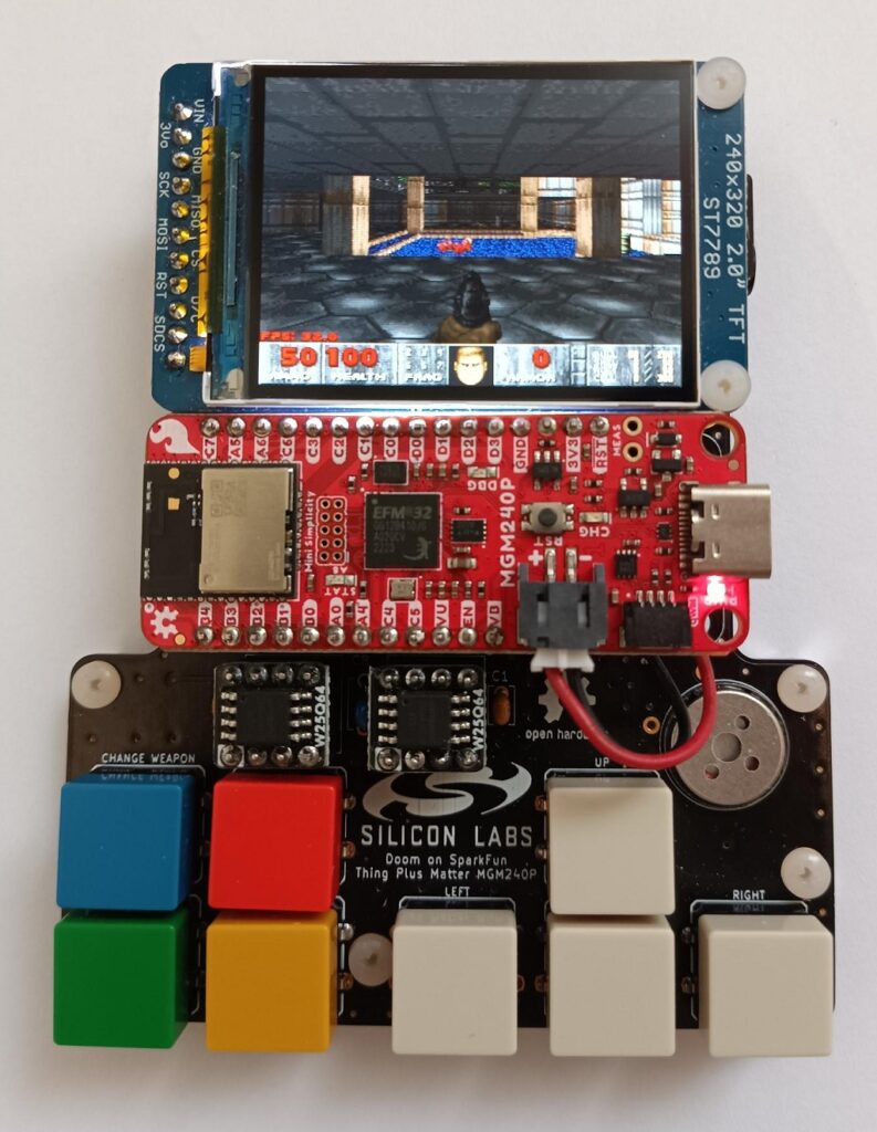
Last year, we ported Doom to the Sparkfun MGM240P Matter board, and for that project, we designed a DIY minimalistic handheld gaming console. That console included only the minimum amount of hardware to play Doom. For instance, it had 16 MB of external flash just to hold the commercial WAD and just 8 buttons. Noticeably, 8 buttons are quite limiting even for a game as simple as Doom, because for some functions (such as menu, map, strafe) we had to use some button combinations. Additionally, that board had only a small speaker for mono audio. Stereo audio was available only through the 3.5 mm Jack, to be connected to amplified speakers. Battery operation was granted by the built-in battery support on the Sparkfun MGM240 Matter board.
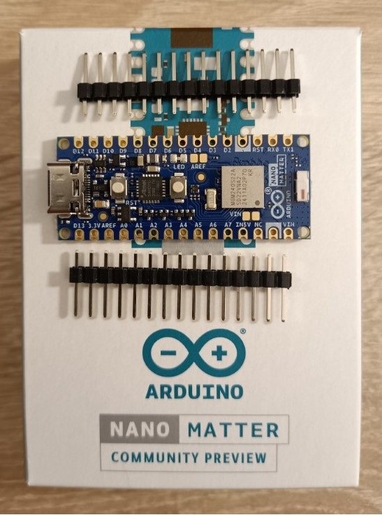
This year, even Arduino released a board based on the MGM240 series: the Arduino Nano Matter board. This board is based on the system-on-a-package variant MGM240S, which is largely compatible with the MGM240P, as we will see later. Since this new board has more I/O pins we wanted to create an improved version of the past console, addressing some of the limitations of the previous project.
Beside the different number of I/O pins, the other differences between the two boards are:
- The Sparkfun matter board includes a battery charger with I2C fuel gauge, an SD card reader, a QWIIC connector and an On-board J-link compatible debugger. The Arduino Nano Matter has an RGB LED, and a user pushbutton.
- The maximum power is 10 dBm (Arduino) instead of 20 dBm (Sparkfun)
- The MGM240SD22 (Arduino Nano Matter) has an ML/AI accelerator, which consists of a matrix vector processor (MVP).
- The Arduino board follows the smaller nano form factor, while the Sparkfun board use the feather one.
Both the MGM240P and MGM240S have the same set of peripherals (excluding MVP), same memory and same core, so, as we mentioned above, they are almost 100% compatible. This means that previous software (read: Doom!) shall run with very minor changes, limited to radio configuration and pin routing.
In designing the new board, we wanted to keep the same philosophy: we shall only use through-hole devices or pre-soldered modules, so that even beginner can mount it. The additional I/Os can be used to increase the number of pushbuttons and/or adding analog joysticks.
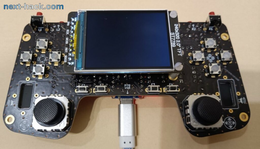
A Quick look
The architecture is very similar to the board we made last year.
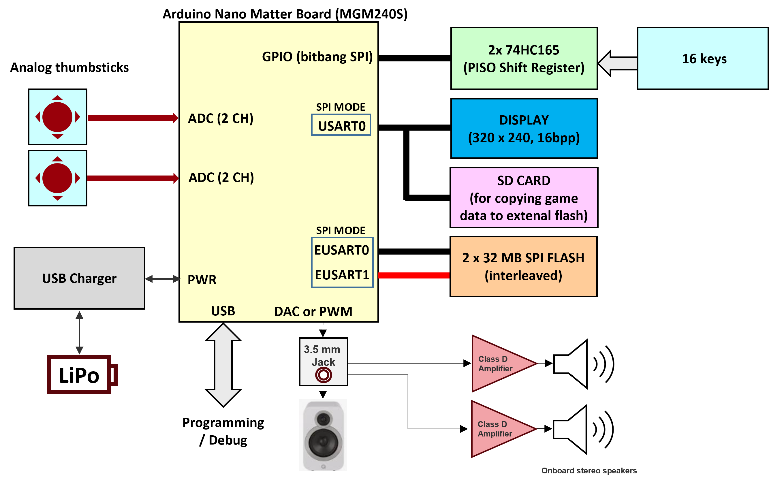
The only changes are:
- There are two analog joysticks. This was made possible thank to the larger number of I/O.
- There are 16, instead of 8 keys. This is achieved using 2 cascaded 74HC165 shift registers instead of just one.
- We increased the flash size to 32MB. This will be useful in the future…
- We now use 2 class D audio amplifiers, for powerful stereo audio.
- The Arduino Nano Matter does not feature an internal battery charger. So, we added an external module.
- Backlight can be controlled. If you want to do this, you must short the AREF SMD jumper, and feed there a PWM wave.
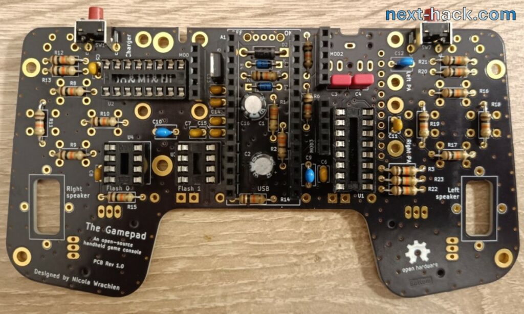
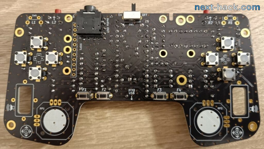
This is the circuit diagram of The Gamepad.
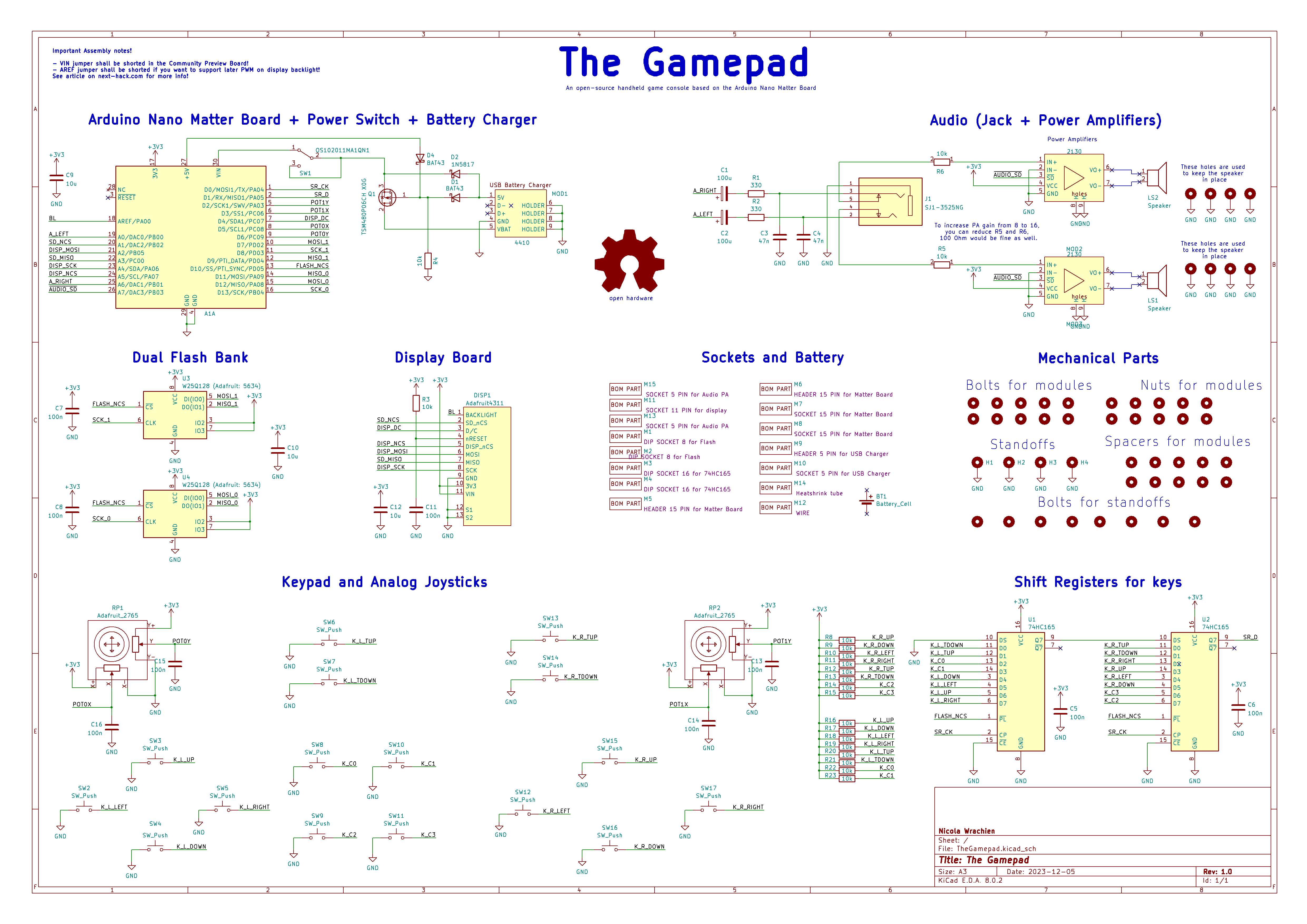
Regarding the charger section, we had to use 3 diodes and a pMOSFET. We use these to make sure that the correct power source is selected (battery or, 5V from USB, when available).
Noticeably, we had used a pMOSFET which is extremely overrated. However, this was the smallest through-hole pMOSFET we could find capable of handling about 1A peak required for the board. We could not find any device in TO92 package with enough current capability and low enough RDSon. If we had used SMD components, we could have found hundreds of SOT23 sized device with good parameters.
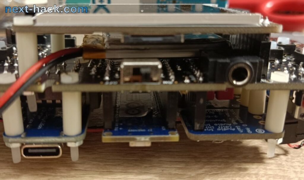
Remarkably, there will be two USB ports. The top one is for charging. The bottom is for debugging. Noticeably, the debugging port also powers the device, and it will do regardless of the position of the main switch.
Like the previous project, the display uses the USART0 in SPI mode, while two SPI flash ICs are used to increase bandwidth, as they will be used in parallel. Note that the two flash ICs must have the same size, because we will interleave the stored data there.
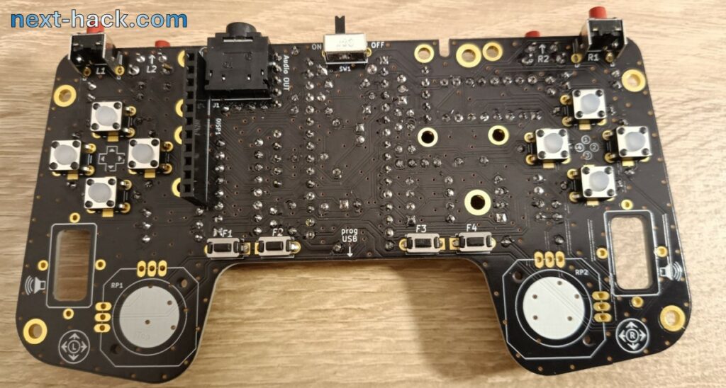
Building
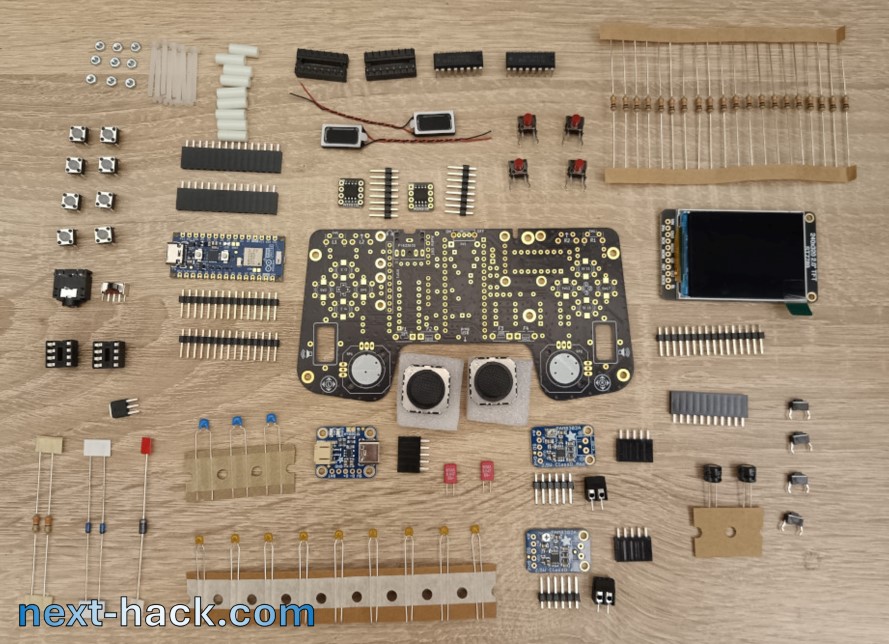
Soldering the board is relatively easy, though we think that some suggestions might be still useful.
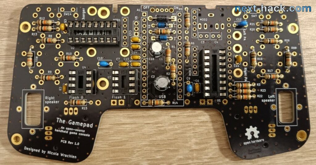
first start mounting the components on the backside, in order of height.
For instance, start with the two smaller diodes, followed by the resistors, the bigger diode, the 100nF caps, the IC sockets, the 10uF caps and the 100uF caps, and finally the polyester caps.
Then we suggest mounting the two sockets for the Arduino nano matter board. Make sure they stay veritical by pressing onto a flat surface.
Then you can proceed with the pMOSFET. We suggest to do it now as this allows to have a small standoff from the board. Also doing it now, before the other sockets, allows to easily place the MOSFET.
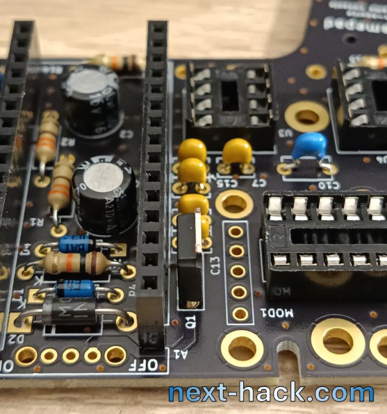
Then you can mount the other 5-pin sockets, and finally the bottom lateral pushbuttons.
Congratulation, you are at half the way !
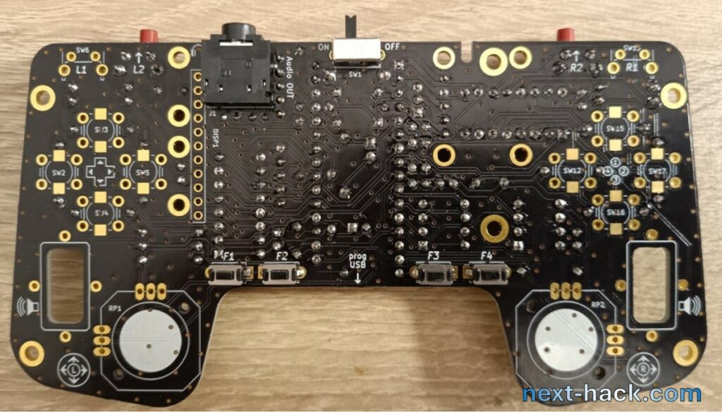
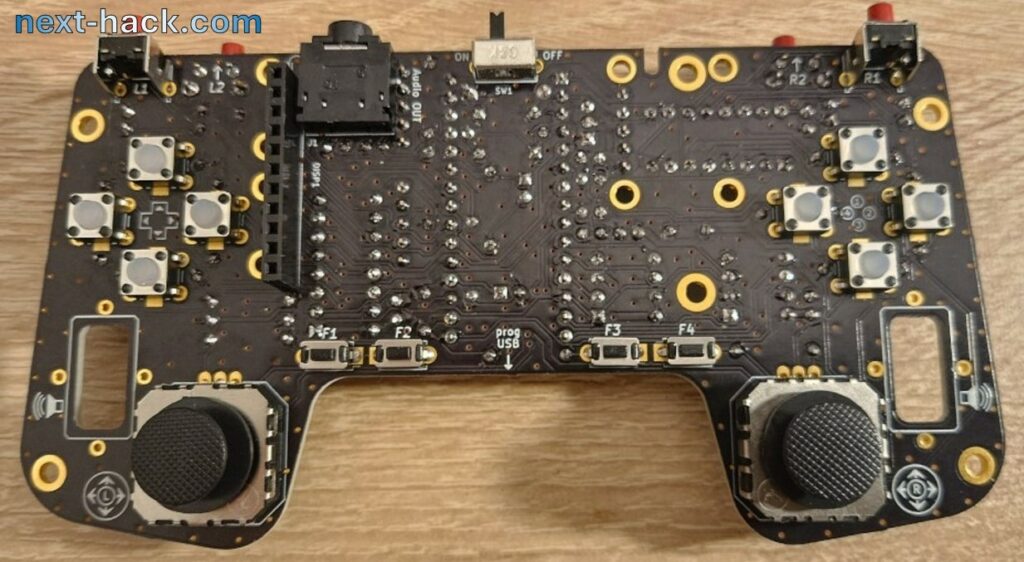
Now you can flip the board and mount the pushbuttons on the bottom (F1-F4), followed by the top slide switch, the audio jack (watch out not to damage the nearby connector).
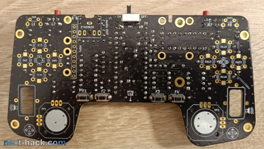
Then you can solder the d-pad pushbuttons. We used the silicone type because they feel much better with respect to plastic ones. We have provided the pads also for SMD silent pushbuttons if you prefer quiet pushbuttons.
Now, this is a good time to start soldering the nano matter board.
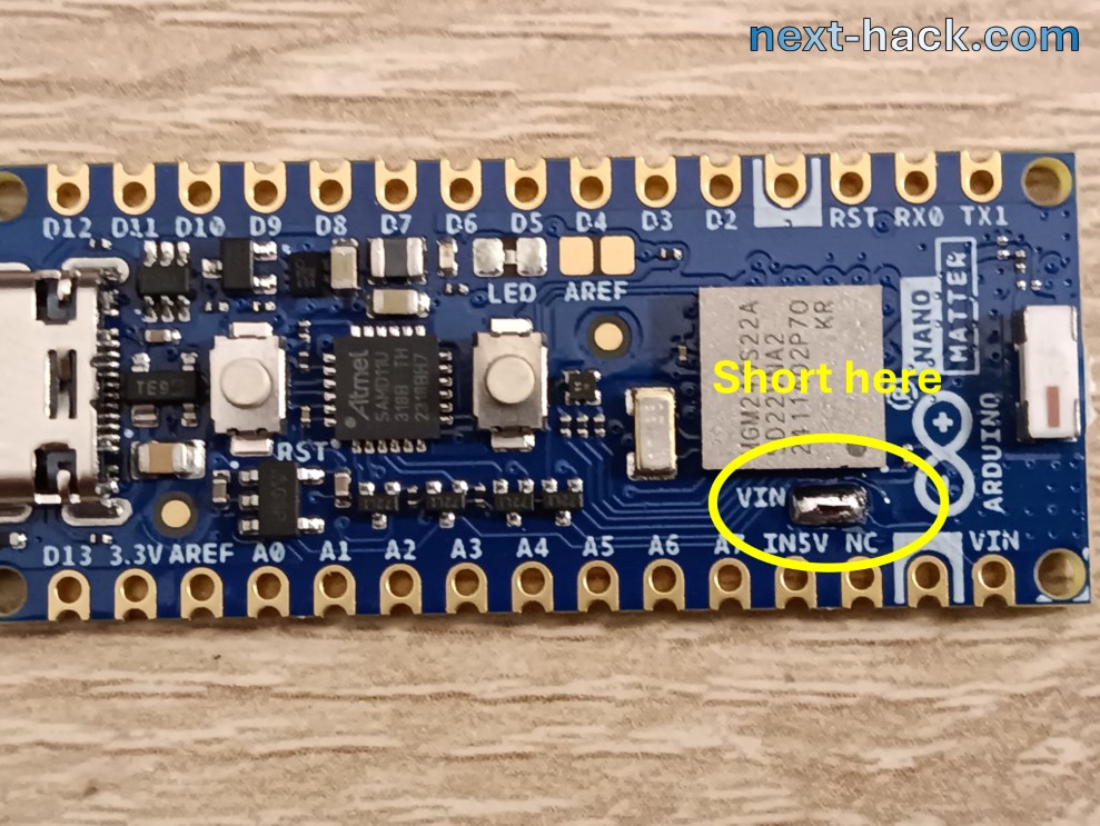
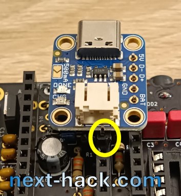
First of all, if you are using the Arduino Nano Matter community preview, you must short the 5V-In SMD jumper. To do this, put a drop of solder on the first pad, then on the second, and then add one in between: a single blob will form shorting the two pads. If you don’t short this pad, the Arduino won’t be powered by the battery or when you connect a USB cable to the charger.
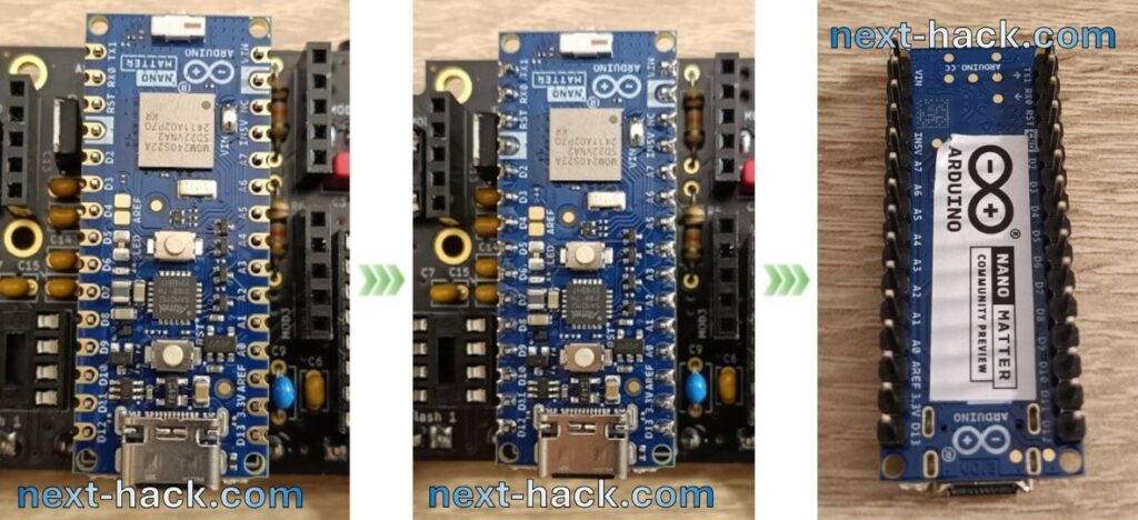
Then, you need to solder the headers.
We suggest to place the headers in the 15-pin connectors you have already mounted and then insert the Arduino Nano Matter board. This will make sure that it will fit nicely later. Be careful with the soldering iron!
In particular, watch out for the following:
- not to damage components on the Arduino board.
- not to insist too much with the iron or you will melt the connectors: you won’t be able to remove the Arduino board anymore.
If you don’t want to risk to ruin the socket, then you can try soldering the board by simply laying it on a flat surface, but the result might not be as good. Other solutions are mounting temporarily the headers and board on a breadboard or some prototyping board.
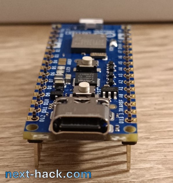
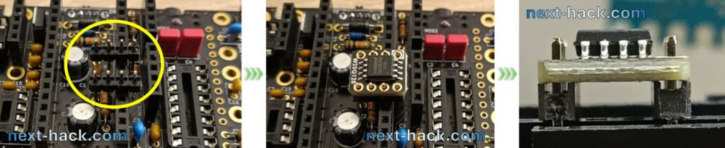
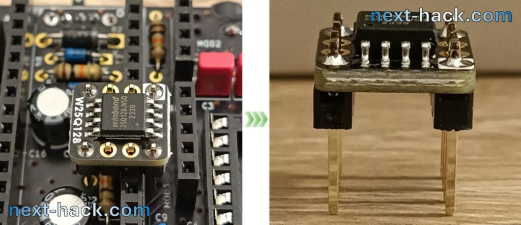
Let’s now solder the flash modules.
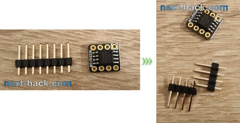
We suggest to use a similar trick, as we show below. This ensures that the headers are perpendicular to the flash PCB.
After you solder the 4 edge pads, you can remove the little PCB and finish the other 4 in more comfortable position.
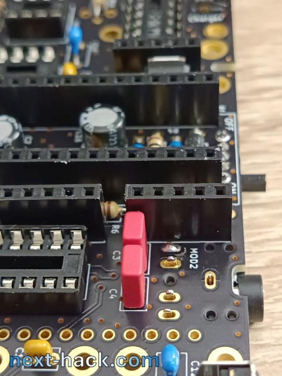
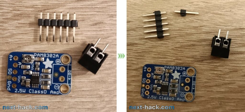
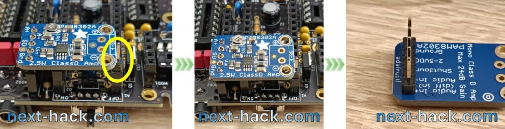
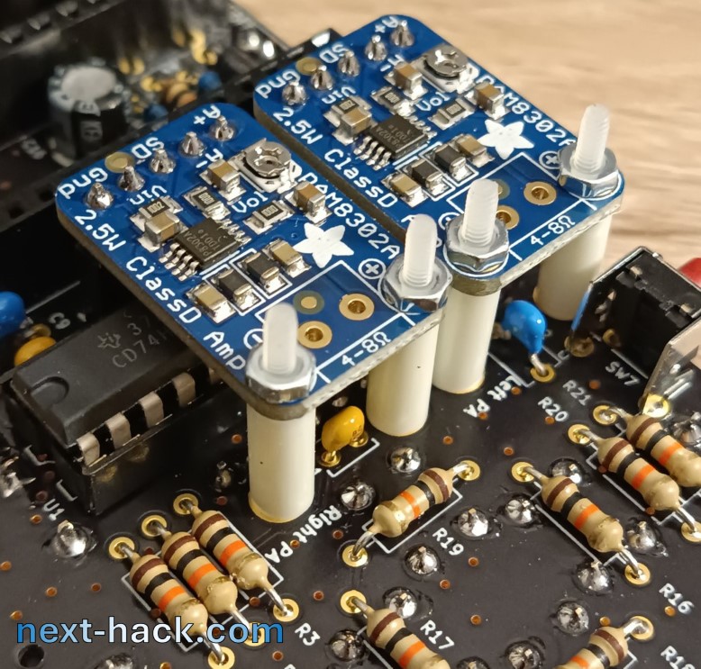
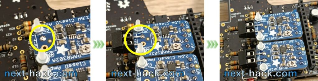
Now it’s time for the two class D amplifier modules.
The header provided is 6 pin, while the module takes only 5. Carefully use one or better two pair of pliers (or even a cutter) to separate the 5 pins. Do not discard the single pin, because we are using it as temporary spacer for soldering the boards like we show below. Also, do not mount the screw connector yet!
Instead of dealing with the charger module, let’s now solder the display connector as shown below. The reason will come clear in few seconds.
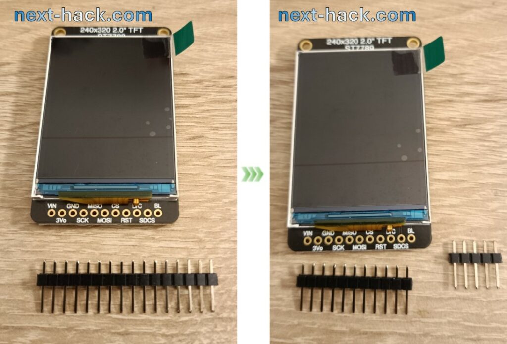
After the connector has been put in place it’s time to solder the header on the display board. The display provided by adafruit comes with a 16 pin header. You can easily separate it to one 11-pin piece and one 5 pin piece you can later use for the charger module. That’s why we said not to solder the charger yet!
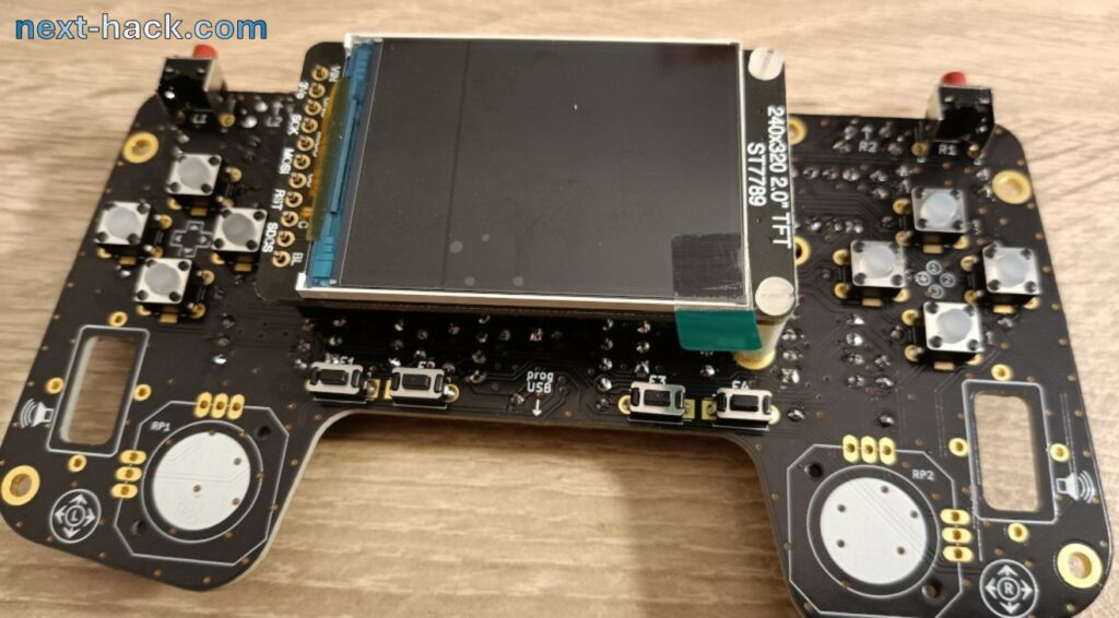
To solder the display, we suggest you to mount it on the 11-pin socket, and temporarily use two plastic spacers, to keep the display horizontal, and the solder the 11 pins.
After you have soldered (be careful!) the display, you can now remove the module and solder the charger board using a similar trick we used before for the audio modules.
You can finally solder the two analog thumb-sticks: that should not be too difficult. Just make sure they are in place by gently pressing the board while soldering.
Almost done! Now the most difficult part comes. Mounting the modules (no kidding!).
You have now to put in place the two shift registers (74HC165) ICs, making sure you follow the correct orientation.
The class d amplifiers are relatively easy to fix. You can simply hold the screw with a screwdriver and turn the nut, or vice-versa, you can hold the nut and turn the screwdriver. Yes, you can also use two tools if you have big hands.
The display part is more complicated because underneath there will be the charger.
We suggest to first mount the spacer for the top display hole. However do not tighten it now!
In this way you can instead put and secure the spacers of the charger. If you want to use a battery and you want its wire to go underneath it, this is the time to place the battery as well. You can do it later but the cable will have to go around the spacer: we left a little bit of room for the cable.
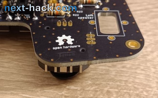
After everything is mounted, let’s fix the speakers. Those little speakers have a top double sided tape which is rather strong. Remove the white protector foil and the accurately align the speaker to the board. Once you are happy with alignment, press firmly, and that’s it.
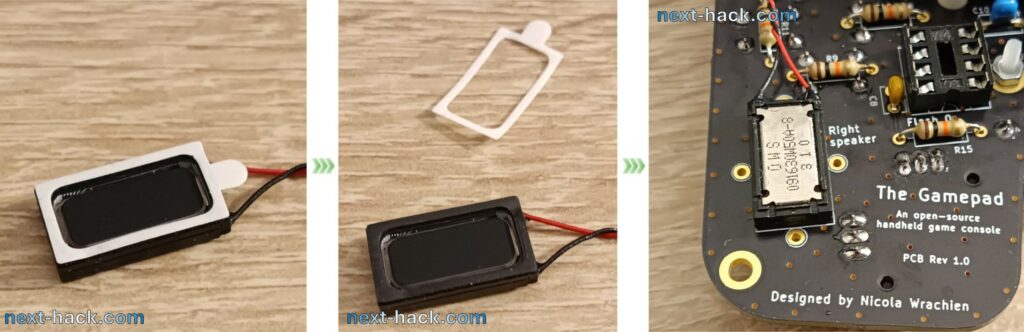
You might wonder what’s the purpose of the 4 pads around the speaker: these were placed in case the adhesive was not strong enough, so we would have soldered some wire to press the speaker on the PCB. However, we found these were not necessary at all.
Now you have to solder to the amplifiers the screw terminal block provided with it. We wanted to reduce the height so we are mounting it in a very unusual (and ugly, we know) way. Feel free to mount them as you wish.
To mount like we did, simply presolder one pad, with some solder. Then by keeping the soldering iron on the pad, put the connector so that it stays in place. You might refine the joint later. Before you do this, solder the other terminal, and then refine, if needed, the first joint.
Now, the left speaker (which is on your right!) can be mounted directly to the screw connector. We suggest you to strip the wire by about 6 mm and then create a u-shaped bend, to improve contact strength. If you don’t do this, the contact might be too loose, even by strongly tightening the screws. (Note: do not force too much on the screw, as the mounting method we used only relies on the relatively weak strength of the solder joint and pad.
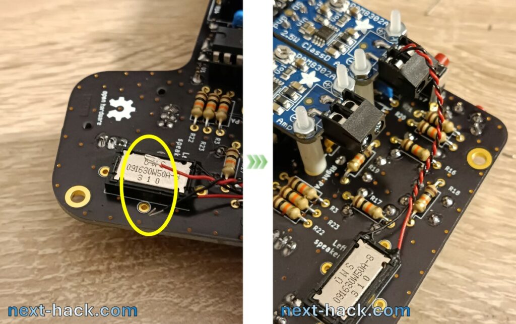
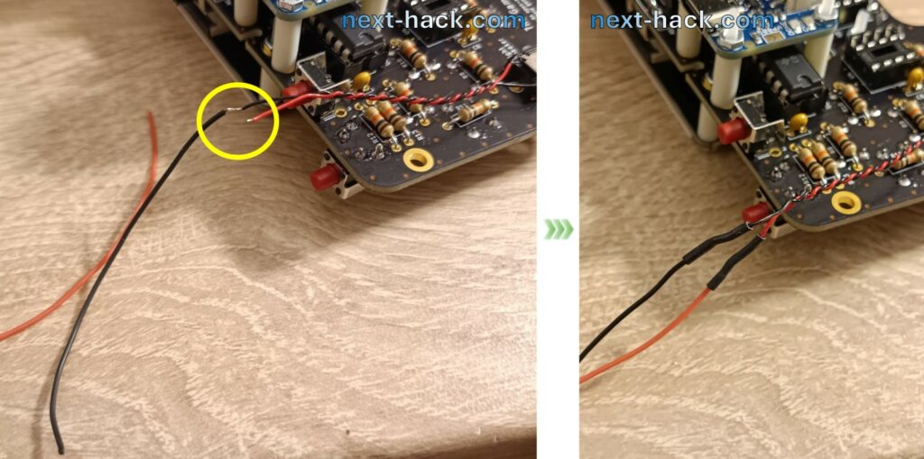
The right speaker (on the right!) requires some cable length extension. We used some wires with silicone insulator for that and some thin heat shrink tubes to isolate and secure the joint. On the connector side, the wire shall be still stripped by 6 mm
Last thing: remember to insert the flash IC modules and of course the Arduino Nano Matter board. Please, respect the orientation!
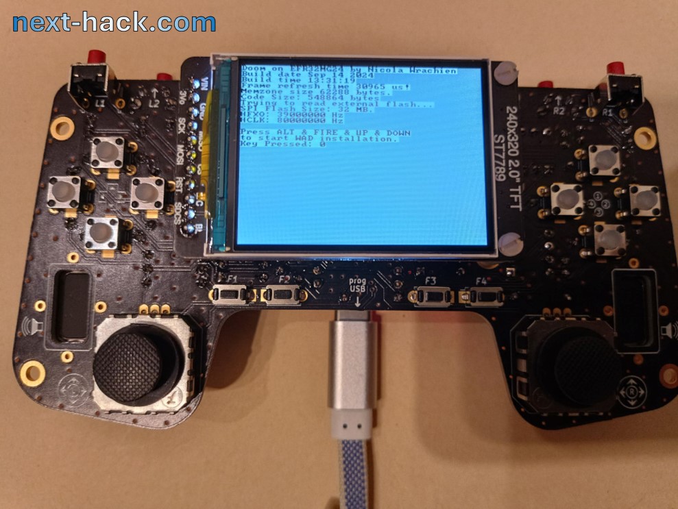
Now it’s done! If you power it now, you will get:
- Smoke: you really screwed something hard.
- Nothing: this is normal, there is not firmware programmed on the board! Yet!
Does it Run Doom?
It’s time to put something there! What shall we use?
What about Doom? We have recently updated the Doom repository to support this board!
Programming
- download and unzip (or clone) the Doom on MG24 with BLE repo somewhere on your pc (e.g. C:\mydir).
- download and install latest Arduino IDE. We just use it just to install the programming tools. If you want you can use it as well to develop your applications/games on this device as well, but for Doom we used Simplicity Studio.
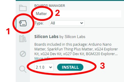
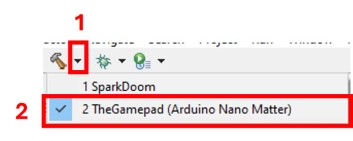
- to install the programming tools, open the Arduino IDE and install the support to the Arduino Nano Matter board. To do this, follow the instructions of the picture below.
At this point you have two ways, a short and a long way.
Long way: build the source and flash.
This is useful when you also want to modify the code. To do this:
- Download and Install Simplicity Studio 5 from Silicon Labs.
- Once installed, open simplicity studio.
- Install the GSDK 4.3.2. To do this: Select from the Help menu the “Update Software” entry. The installation manager window will appear. Select SDKs, scroll down to “Gecko SDK – 32-bit and Wireless MCUs” and download the GSDK 4.3.2. Note that other versions might require some changes and these are not supported on this project.
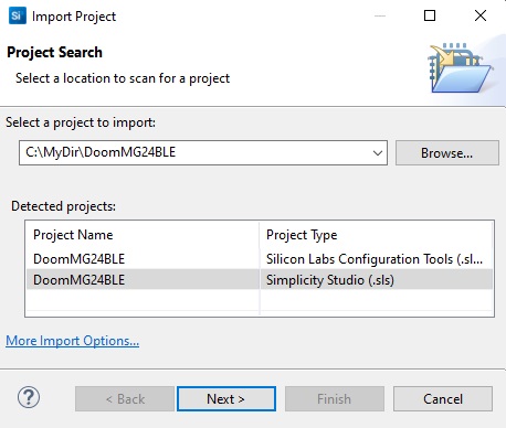
- Once installed the GSDK 4.3.2, import the project by selecting “Import…” from the File menu. The import window will appear. Click on “Browse“, navigating to the location where you placed the Doom project files, and going to the Doom subfolder, then select the sls file, click on next, and follow instructions. Make sure the SDK you select is 4.3.2 and toolchain is GCC 10.2.1.
- In the project explorer pane (on the left), open the .slcp file, by double clicking on it.
- On the right a window with three panes shall open. On the first one (Target and Tool Settings),scroll down and select “Change Target/SDK/Generators” .
- Select/type the part number MGM240SD22VNA, and click on “Save“.
- A window will appear asking if you want to keep or change some configuration files. Make sure that “keep my files” is selected on all entries, then press ok.
- build the code by selecting the project on the left pane and clicking the arrow close to the build icon (the hammer icon), and then selecting the correct build configuration:
After some time the build shall be completed. - Now you must complete the steps of the “Short Way” described below.
Short way: simply flash the latest binary.
- connect the board to the PC, using the debug USB port (i.e. Arduino Nano matter USB port. DO NOT USE THE CHARGING PORT!).
- find the subdir “
/TheGamepad (Arduino Nano Matter)/” and double-click on the bat file “CopyToArduinoMatterBoard.bat”. This will call the openOCD programmer installed with the Arduino Nano Matter board support (point 3 of previous list). You can instead open a command prompt, navigate to the debug directory, and enter:%USERPROFILE%\AppData\Local\Arduino15\packages\SiliconLabs\Tools\openocd\0.12.0-arduino1-static\bin\openocd -d2 -s %USERPROFILE%\AppData\Local\Arduino15\packages\SiliconLabs\Tools\openocd\0.12.0-arduino1-static\share\openocd\scripts\ -f interface\cmsis-dap.cfg -f target\efm32s2_g23.cfg -c "init; reset_config srst_nogate; reset halt; program {DoomMG24BLE.hex}; reset; exit" - Now you must continue to: wad upload.
Wad upload
Regardless the method you chose, you must now download and convert a WAD file . For this, follow the instructions provided in our previous article. This WAD file must be then uploaded to the external flash of the gamepad.
- After you have converted the WAD, name it wad.wad, put it on an sd card.
- Insert the card in the slot underneath the display.
- Reboot the gamepad and press the key combination, to start wad copy procedure (press and hold: up-down on the left d-pad, and button 3-4 on the right. See silkscreen). Note that the external flash erase operation might last up to 100s. After erase, actual upload will occur, with a speed of about 250kB/s.
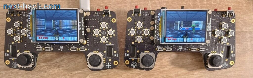
When everything is done, the device will reboot, and Doom will run!

Note, the first time Doom runs, it will take some time to load the map. Refer to the previous article for more information about.
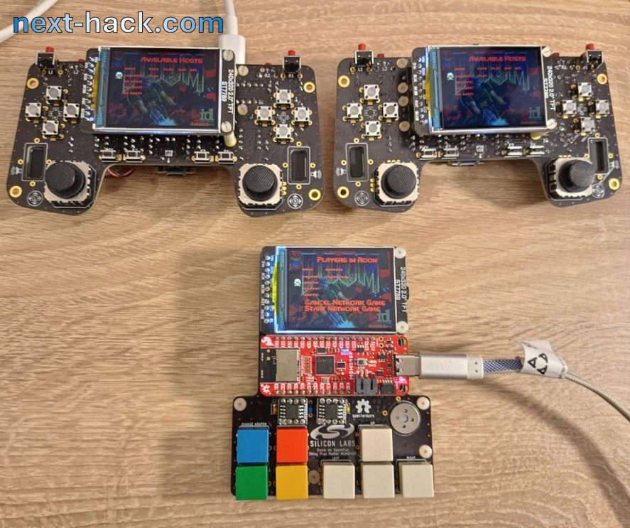
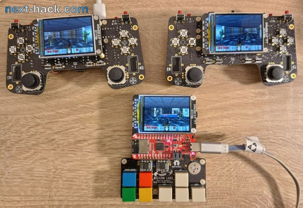
But what is better than playing Doom? A multiplayer match!
Yes, the multiplayer is compatible with the old Sparkfun board.
Case
We will design later some case you can 3D print. This will take us some time, so stay tuned 😊.
Design File Downloads
You can find the KiCAD PCB and SCH files of The Gamepad here.
Note: we don’t sell hardware/kits/components, so don’t ask us to sell you one. All the original files (source and schematics) are provided for free in the repository. You can buy all the components from your preferred distributor and have the PCB manufactured.
Conclusion
Although the board runs multiplayer Doom, this was not our goal. The real goal will be clear on next article 😊.
See you on the next-hack!