
One major problem of rechargeable batteries is that they cannot be completely depleted, without actually damaging them. And many flashlights are thought for disposable batteries, where you want to use even the last drop of energy. If you use rechargeable batteries on such flashlights, the battery will be permanently dead once it has been depleted. A battery under-voltage protection is therefore required.
In this project, we want to build a powerful flashlight, powered by a 12V sealed lead-acid (SLA) battery. Such batteries are quite robust and easy to find. Still, we want an electronic circuit that will disconnect the lamp if the battery voltage goes below the threshold voltage of 11.5V. As we will show in the followings, by varying the resistor values, you can choose different cut-off voltages, which is useful if you want to extend the safety margin, or if you need to adapt the circuit to a different battery, such as a 24-V SLA battery or a 10.8 – V Li-Ion battery pack.
A simple solution would be a rocker-type switch, in series to a protection circuit. This solution has the drawback that the current (including the inrush current) will flow into the switch. This means that the switch contacts will have to be rugged, therefore the switch will be somewhat expensive.
However, with a very small and clever circuitry, not only we can avoid battery over-discharge, but also we do not need a power switch, which might cost more than the circuit itself! We will still need a pushbutton, but it doesn’t have to be a power button: any cheap small signal button will be enough.
The circuit uses a positive feedback to self-latch its state. A capacitor stores the opposite of the current on- or off-state, so that each button press will alternatively turn-off or on the flashlight.
We designed the circuit without any heat-sink. This limits the current capability to about 4 A with our MOSFET, which corresponds to a maximum 48W @12V. Higher powers can be achieved either mounting a heat-sink or by choosing a MOSFET with a smaller RDS,ON value. In our case, we will use a 18-W lamp, which therefore draws less than 2 A.
Principle of operation
Here is the circuit diagram: download also in pdf format!
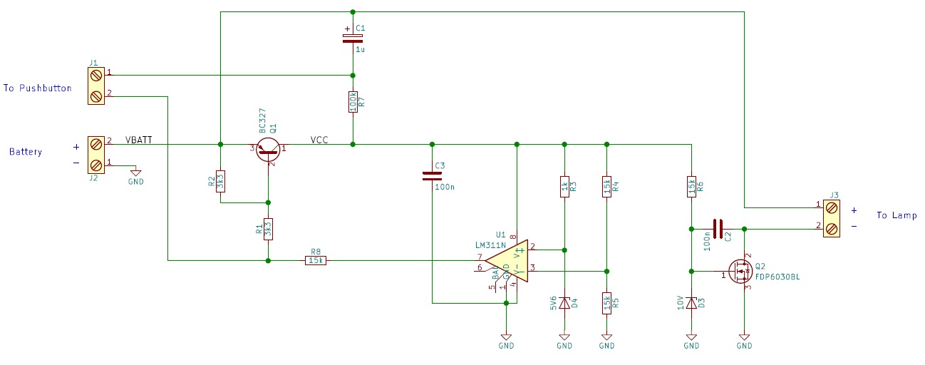
Fig. 1. Circuit diagram.
The circuit consists of two distinct stages. The first stage is the actual latching circuitry, and battery voltage monitor. The second one is a nMOSFET that connects the lamp to the battery.
Let’s analyze the second stage first! When the circuit is on, the gate of Q2 is biased up to 10V, thanks to the resistor and Zener diode. The Zener diode is required if you plan to use this circuit on 24V batteries. Also you need to change the Zener diode, if the maximum admissible VGS voltage of your MOSFEET is smaller than 12V (remember to use some safety margins! Do not choose the Zener voltage too close to the absolute maximum gate-to-source voltage!).
The capacitor C3 slows down the turn-on of Q2. This is particularly useful if you are going to use a LED lamp, which might have large a built-in input capacitance. Since the current on a capacitor is proportional to the variation of its voltage, by slowing down Q2, we will limit the inrush current.
Now, let’s go back to the first stage.
Normally, it’s in the OFF state: R2 pulls the base of the PNP transistor Q1 to VBATT. The open collector output of U1 is pulled high through R1-R2-R8. U1 is unpowered (as well as the remaining part of the circuit). The capacitor C1 is charged at VBATT, through the resistors R7, R4, and R5. In other words the negative terminal of C1 is at 0V.
As soon as we press the button, we connect the negative terminal of C1 to the connection of R1 with R8. This will actually bring a brief 0V pulse to that node, and a current will flow out of Q1’s base. Therefore Q1 will turn on, providing power (VCC = VBATT-VSAT, where VSAT is Q1’s saturation voltage) to the comparator U1, and the other part of the system connected to Q1’s collector (VCC).
Now:
- R7 discharges C1, as now VCC = VBATT-VSAT (the positive terminal of C1 is connected to VBATT. The final C1 voltage will be VSAT, i.e. very low).
- The non-inverting input of U1 is polarized at 5.6 V (Of course, assuming that VBATT is much larger than 5.6V!)
- The inverting input of U1 is polarized at
\cdot\frac{R_5}{R_4+R_5}")
If U1’s inverting input is at a higher voltage than is non-inverting one, then its output will be low, keeping Q1 in the ON state. This occurs when: 
In other words, we are using a positive feedback, to keep our device in the ON-state.
If we press again the button, we connect C1 to R1 and R8, forcing there a voltage pulse as high as VBATT-VSAT.
This will turn-off Q1, which will remove the power to the system. Here’s again comes positive feedback! The voltage at the node VCC will quickly drop (before we release the button), so the comparator will turn off its internal output transistor. In fact, after few microseconds the inverting input will be at a lower voltage with respect to the non-inverting input. Since U1’s output transistor is OFF, the base of Q1 will be kept high by R1 and R2, so the transistor will remain in the OFF state, regardless how long we press the button. Since now VCC is 0V, the gate of Q2 is low, therefore the flashlight is off.
Now let’s investigate the battery protection: let’s suppose that the flashlight has been turned-on, when the battery was charged. The voltage of the battery will progressively decrease until the threshold is reached. If, at any time, the battery voltage decreases below the threshold voltage shown above, the comparator will turn off its output transistor, turning off the whole system.
Let’s go for the Next Hack!
Enough talking! Let’s build this circuit!
For this project you’ll need:
- Qty 4: 15 kOhm resistors.
- Qty 2: 3.3 kOhm resistors.
- Qty 1: 100 kOhm resistor.
- Qty 1: 1 kOhm resistor.
- Qty 1: 5.6V Zener Diode BZX55C5V6.
- Qty 1: 10-V Zener Diode BZX55C10 (optional, but recommended).
- Qty 2: 100-nF ceramic capacitors 50 V.
- Qty 1: 1 uF electrolytic capacitor 50 V.
- Qty 1: NPN BJT BC327.
- Qty 1: Any POWER nMOSFET, with RDSOn < 0.1 Ohm, and VGS,MAX > 15V. E.g. FDP6030BL.
- Qty 1: a 8-pin DIP socket (optional, but recommended).
- Qty 1: LM311.
- Qty 3: 2-way screw terminal (optional: you can directly solder wires).
- Qty 1: pushbutton.
- Qty: 5 M3 nuts (optional).
- Qty: 4 metallic hexagonal metal stand-offs (optional).
- Qty: 1 M3 screw.
- A prototyping board. Alternatively you can etch on a PCB the layout.
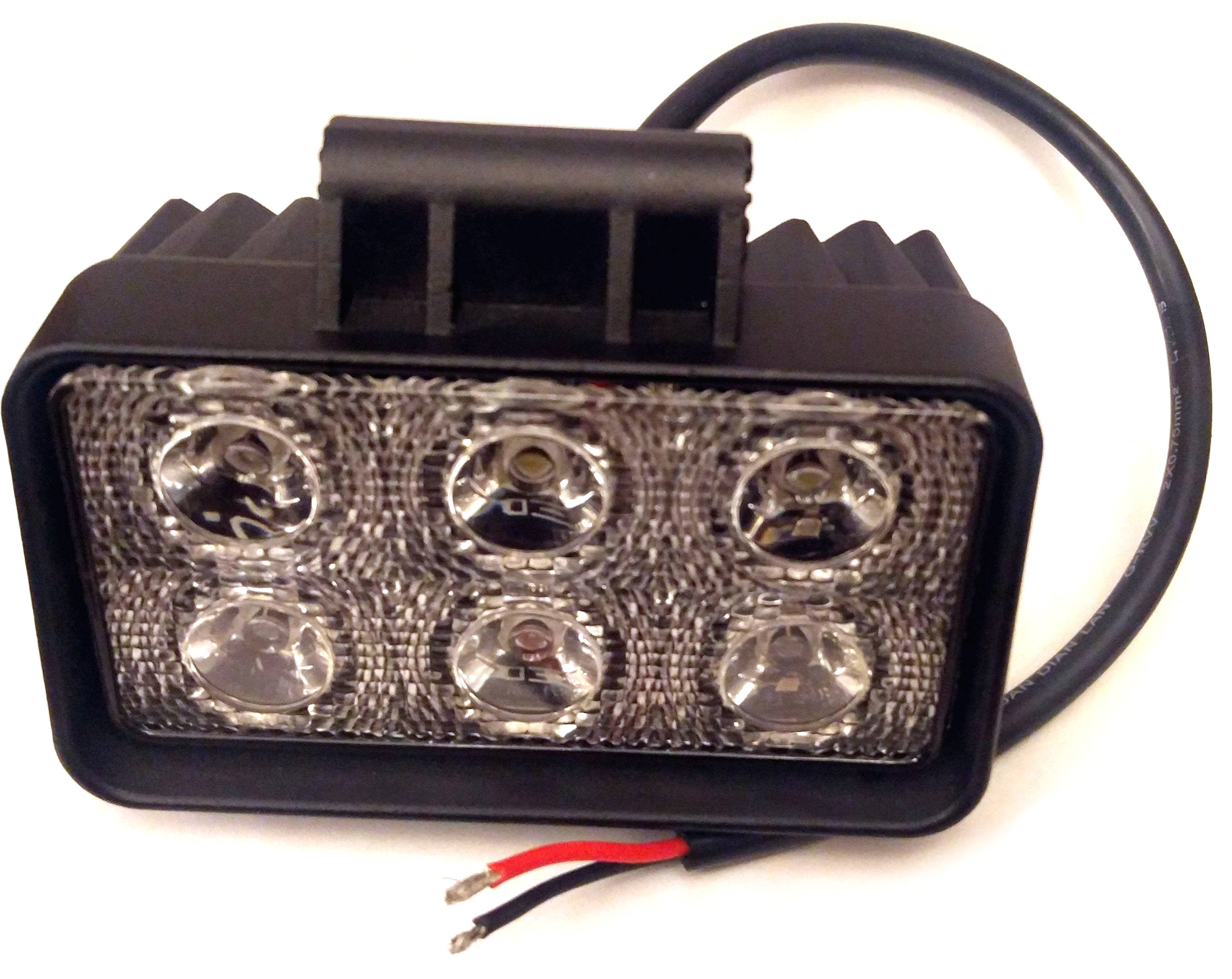
- A 10-18 W 12-V Led floodlight, such as this one on ebay. If you want more light, there is also a 48W version!
- Of course some wire, solder and and a soldering iron!
- A 3.2-mm drill bit.
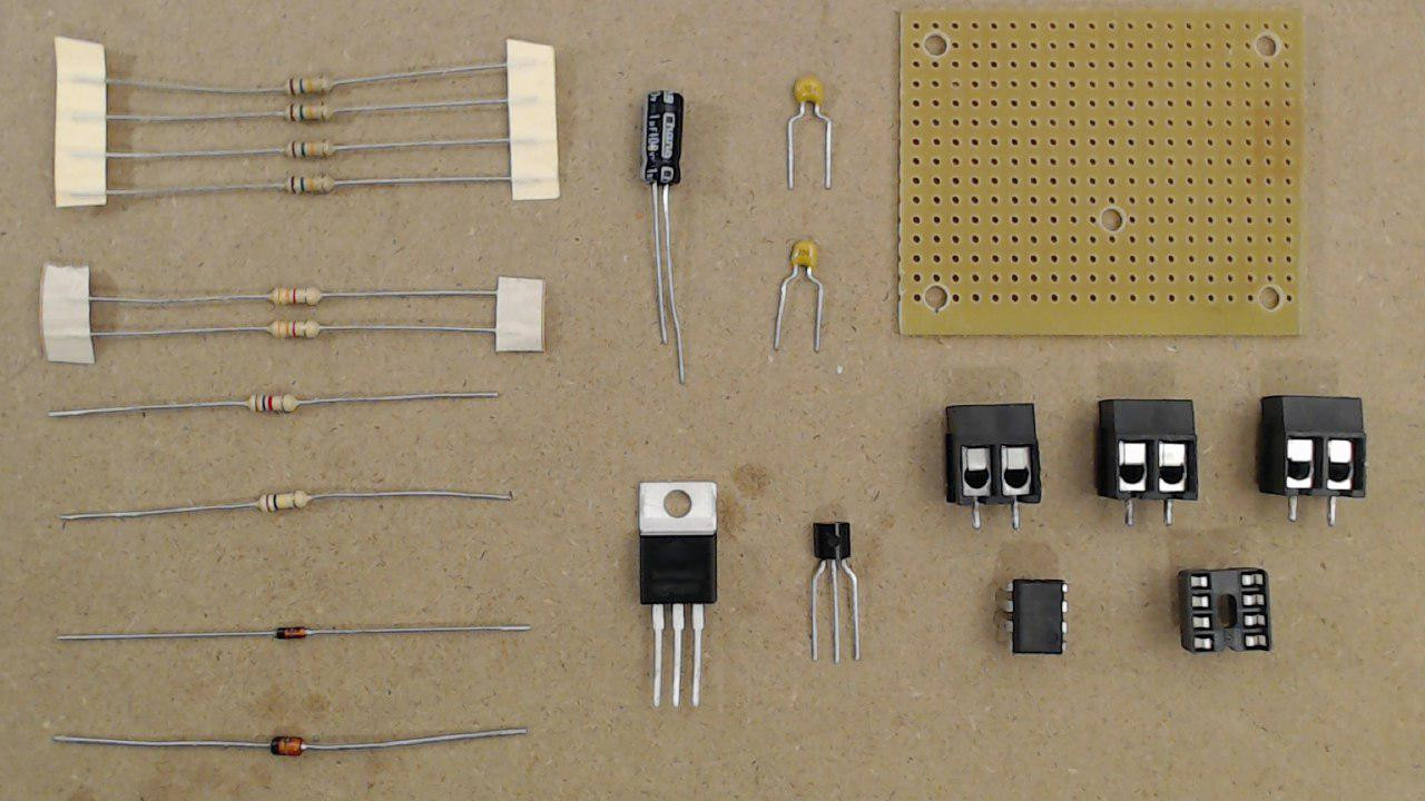
Fig. 2. Components required for this project.
We used KiCAD to make the layout, so that it can be easily implemented on a prototyping board!
You can download the component assembly drawing (the green traces are in the bottom layer) as well as the already mirrored 1:1 bottom-copper image.
If you are just using a prototyping board, here are the two images.
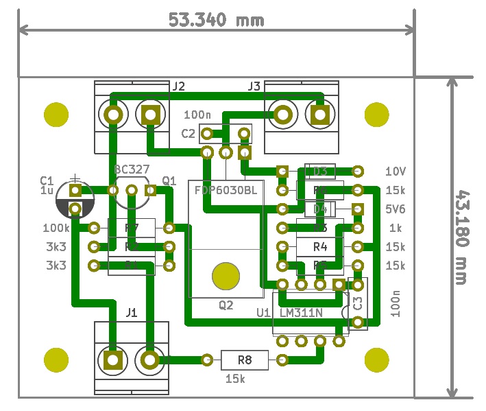
Fig. 3. Assembly drawing.
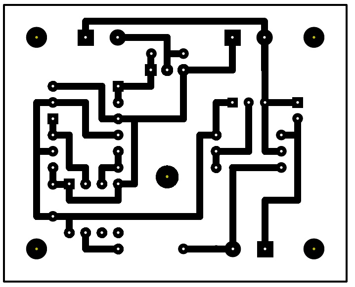
Fig. 4. Bottom layer (already mirrored so that this is what you will see looking the PCB from the bottom side!)
First cut some prototyping board with the dimensions indicated in the layout. You should have exactly 20 x 16 holes! (Actually the bottom row of holes is not used, as no traces are underneath it).
Then, make the 5 holes (4 for the stand-off, 1 to fix the MOSFET) on the board. Note: in the prototyping board, we aligned the hole for the MOSFET to the 2.54 mm grid. This is not necessary if you etch your board. In the image above, the prototyping board is already cut and drilled.
Then mount the components, sorted by heights, according to the layout.
- The resistors
- The diodes
- U1’s socket (do not install U1 yet!)
After that Q2 comes. You have to bend the terminals: you can use a ruler to take the dimensions!
After that you can continue with the other components:
- The two ceramic capacitors.
- Q1
- The electrolytic capacitor
After that you have to mount the screw terminals. On many prototyping boards, the holes might not be large enough. You should use a 1.5mm drill to enlarge the holes.
Now, trim the components terminals and keep them for the connections.
Use the layout image of the BOTTOM side (note: the image already flipped!), and solder the connections as shown here.
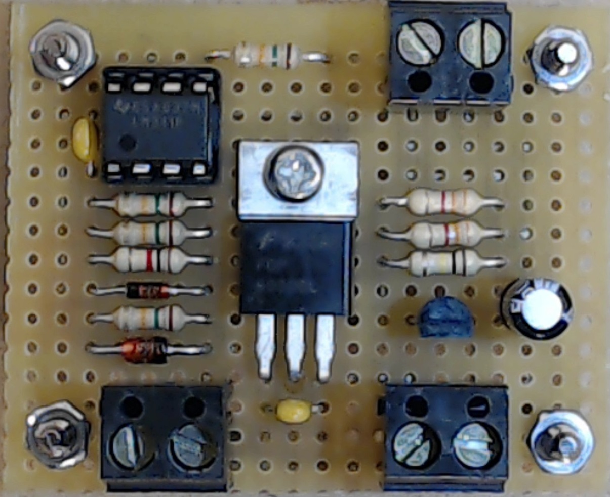
Fig. 5. The complete circuit.
Now the testing phase! We suggest first to use a simple LED + resistor! Connect a push button and connect the battery. The LED should turn on/off at each button press!
We used a regulated power supply and we found that the cut-off voltage is 11.38V. This is very close to the value predicted by the equation 


We hope you found this small project useful. This can be adapted to many other applications. You can also connect a pMOSFET to the output of U1, and having the positive (instead of the negative) rail switched (this is called high-side switch). This might be useful in many cases, where you want to keep a common ground between this circuit and the circuit you are switching.
In the next part we will create a suitable housing for the lamp and battery! Stay tuned!
What’s your next hack?