Introduction
In the Internet of Things (IoT) era, being able of controlling everything is becoming more and more requested. The most common example is the home automation: one would like to control for instance lights, the gates, and even appliances. One could use advanced wireless and custom solutions, but this adds difficulty to the task, and discourages many people. A much simpler way is to connect directly a relay board to a PC/Mac: one can choose his/her preferred high level language programming environment. Relays allow easy and inexpensive control of loads.
How to connect relays to a PC? Of course via USB! An USB-controlled board is a very advantageous solution: you can hook it up to any PC/Mac with an USB port and it also can draw directly the required power from it.
Despite its simplicity, this project will allow you to control up to 12 relays. The chosen relays allow to switch (resistive) loads up to 3A. If heavier loads must be switched, then one can either put a more rugged relay, or can use these relays as a switch, to control bigger relays close to the loads.
The board is USB compliant, as the current consumption with all the relays in the ON state is less than 350 mA.
We used uChip, which is an Arduino Zero compatible board shrunk to a 16 DIP package. This allows us to make a compact design. Actually you might use anything you want that has an USB connection and enough I/O pins.
In this project we also put two pushbuttons which might be used for testing purposes, or emergency buttons, or other things. These functionalities are left open to your immagination!
Part 1 will cover the full project, which allows to control the board using a PC/MAC or even a Raspberry.
Part 2 will cover the USB Host implementation, that allows to connect a 3G dongle, and to allow to control the relays using SMS.
Theory of operation
The device waits for a serial connection on the USB port (CDC). Once a connection has been established, it periodically listens for commands. You might use any baud rate, as the USB device implements a virtual COM port.
The commands are as follows:
Capital letters A to L select the relay(s) you want to turn on or off. For instance ACF will select the first, the third, and the sixth relays. A subsequent 0, will turn off all the selected relays. A subsequent 1 will turn the selected relays on. Any other characters (including lower case a-l and 2-9 etc.) will abort the command.
For instance “ACF1” will turn on relays A, C and F.
If we write “CF0”, the relays C and F will be turned off.
Any combination of relays can be turned on/off simultaneously.
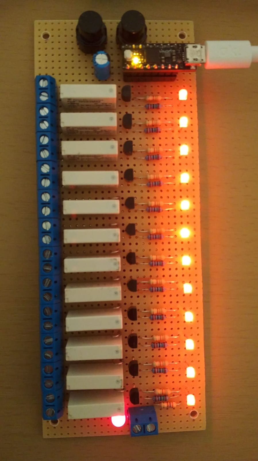
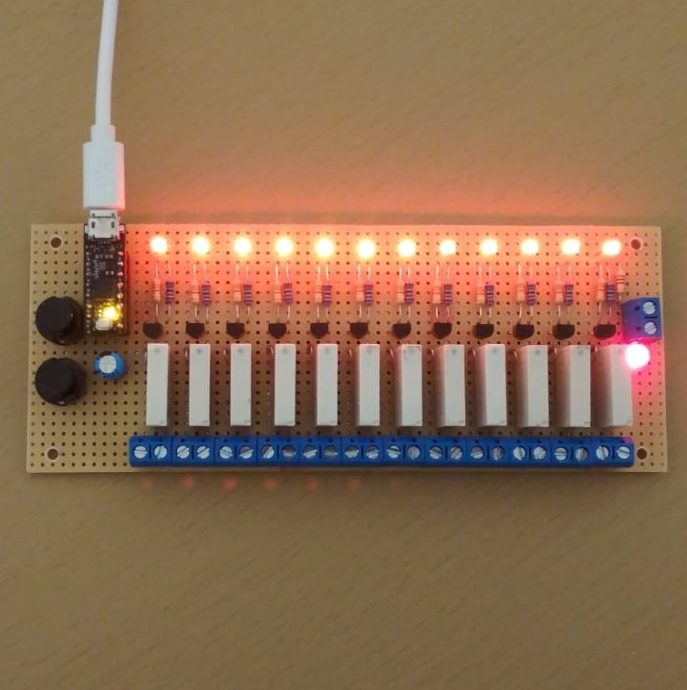
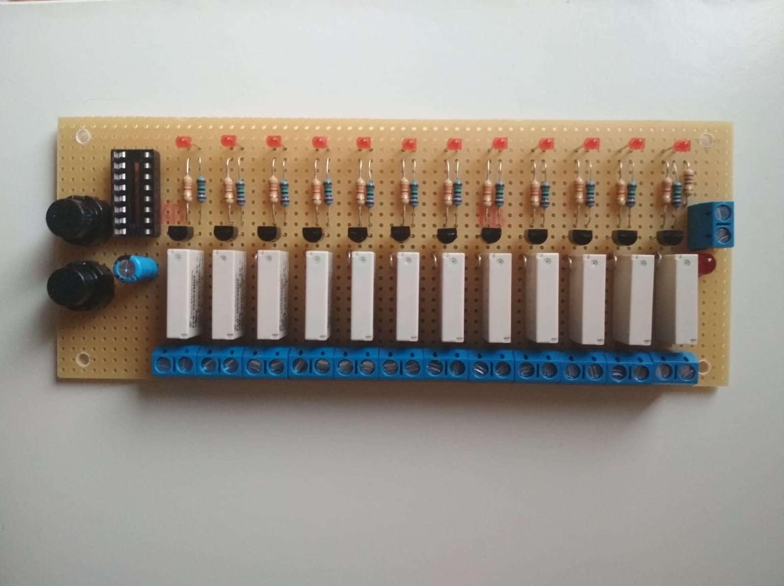
Each relay is connected to uChip using a BJT. The LEDs show the state of the channels.
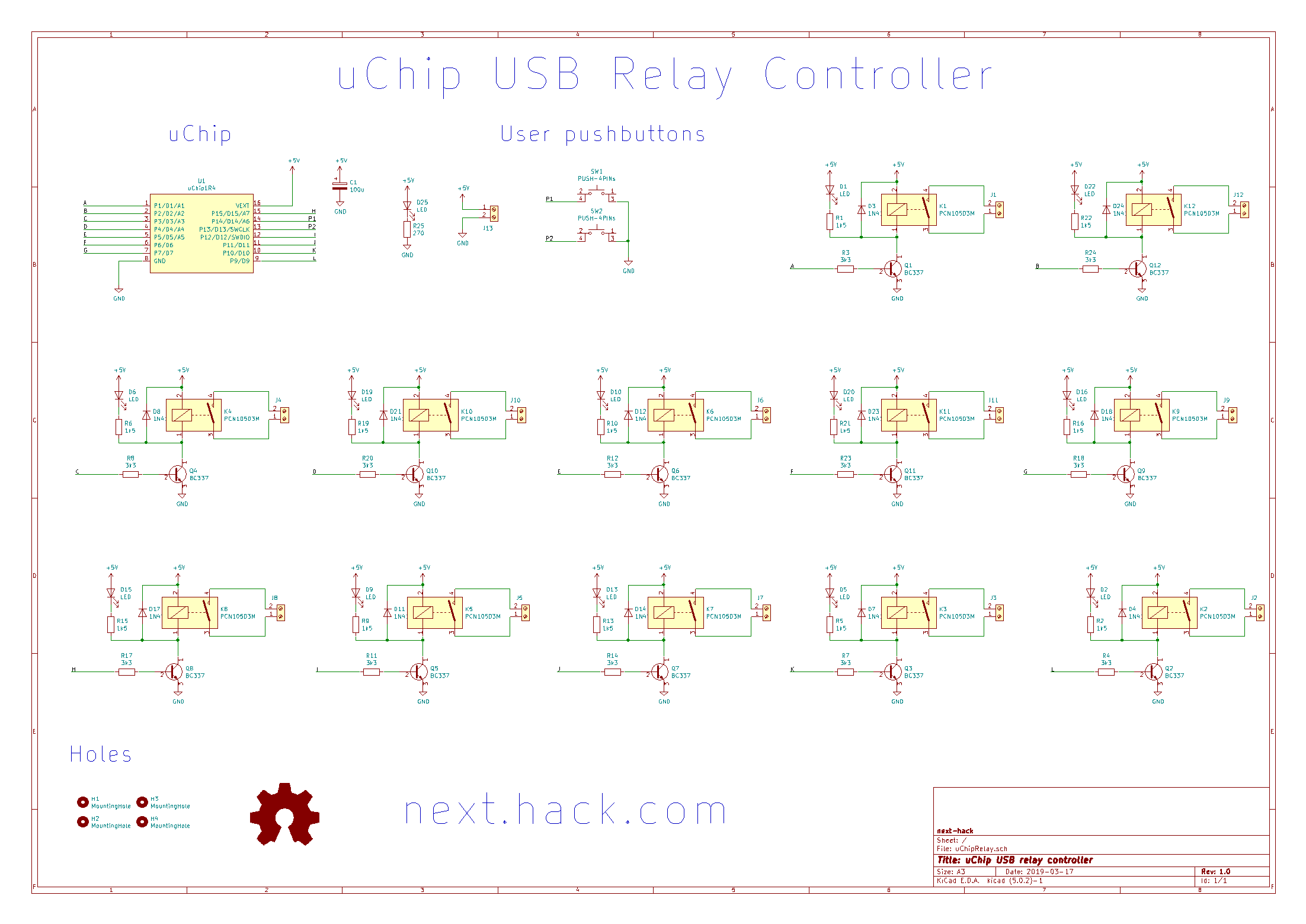
Here is the schematics PNG and here the KiCAD project!
Downloads
Click here for the full KiCAD project.
Click here for the Arduino sketch!
Hardware requirements
- 1x uChip
- 12x BC337-40
- 12x 3.3 kOhm resistor, 5%, 1/4 W, through hole
- 12x 1.5 kOhm resistor, 5%, 1/4 W, through hole
- (adjust value to achieve the desired LED luminosity)
- 1x 270 Ohm resistor, 5%, 1/4 W, through hole
- (adjust value to achieve the desired LED luminosity)
- 1×100 uF electrolytic capactor, 6.3 mm diameter, working voltage > 6.3 V
- 13x 2-poles screw terminal, 5.08 mm spacing
- (the 13th is used if you want to provide the 5V power externally. This will be used also for the second part of this project: being able to use the board by connecting it to an USB 3G dongle)
- 1x 6.35×16 cm prototyping board.
- Of course this measure is not standard, so you might want to buy one 10×16 standard, as we did.
- Not needed if you instead decide to use the layout provided in the KiCAD project archive.
- 1x 5 mm LED. Pick your color!
- We just used red as it was the cheapest!
- 12x 1.8 mm LED.
- Pick your color here too!
- 12x 1N4148 diode
- 12x TE Connectivity PCN-105D3MHZ relay.
- These relays were choosen because of their compactness and low coil drive current.
- KS-01Q-01 pushbutton. These are optional.
- Hexagonal standoff M3 Nylon 6mm (e.g. CBMFTS210A).
- Pay special safety precautions if you use metal standoff instead!
- Hexagonal nylon M3 nut.
- Pay special safety precautions if you use metal nut instead!
- Micro-USB to USB Cable.
- 16-Pin IC socket.
Software requirements
- Arduino IDE.
- A terminal program such as termite or your program.
- This sketch.
Let’s go for the next hack!
In these steps we use a 10×16 cm perfboard. Of course, you can also manufacture the PCB following the layout.
Step 1: prepare the prototyping board
Jump to step 2 if you decide tho make your own PCB!
First measure the desired board size
a. Measure the desired board size.
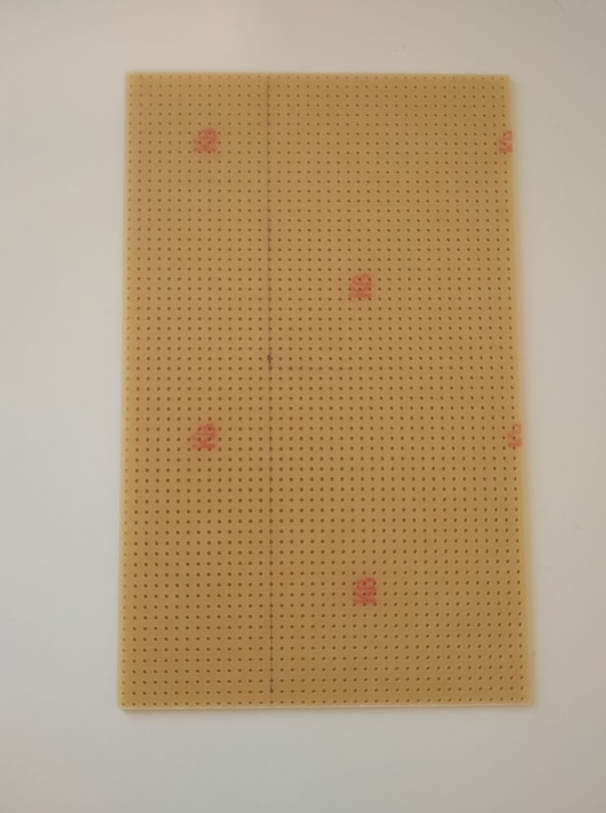
b. Cut the board.
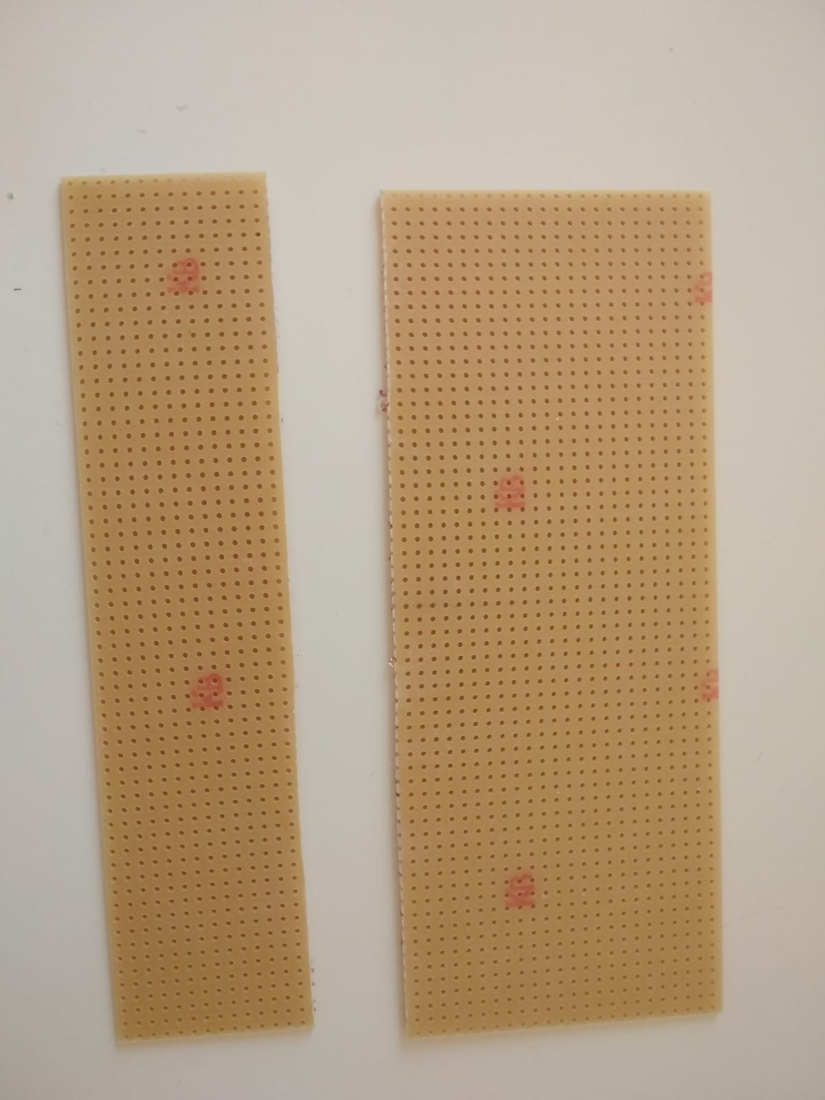
c. Use a file to smooth the edges.
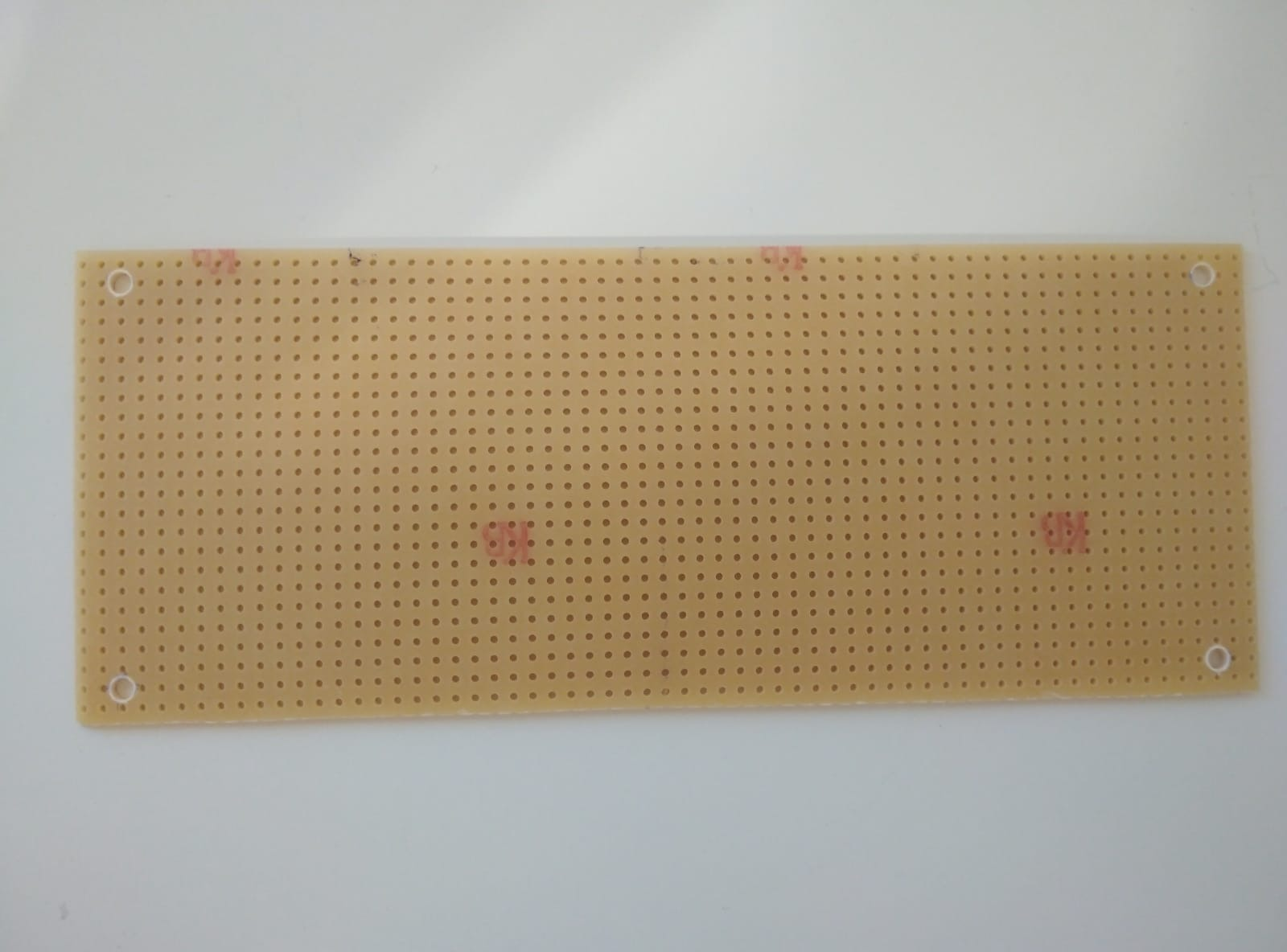
d. Mark the position for the holes.
SAFETY WARNING! If using 110-240 V loads, then place the holes a bit farther than what’s shown here, especially near the screw terminal blocks. Alternatively do not use metal stand-off, but plastic ones as suggested in the component list.
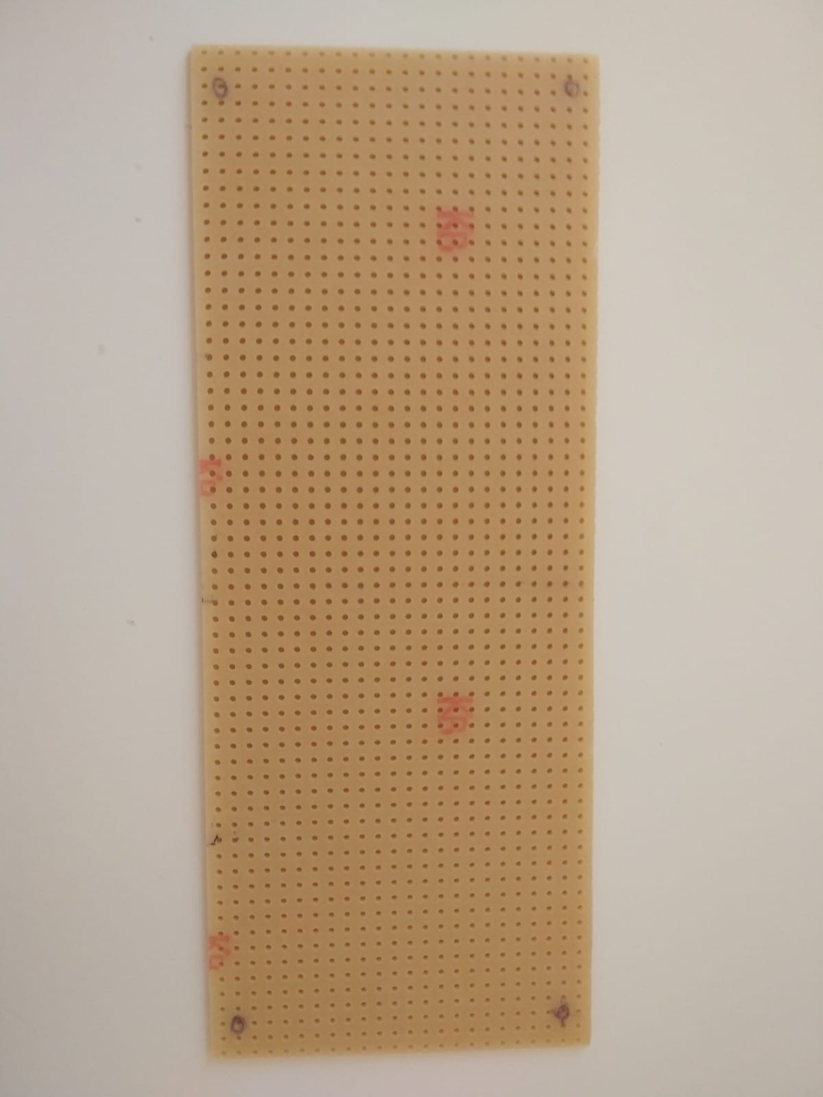
e. Drill the holes.
Step 2: solder the components
Solder all the components, in order of height. Resistors, IC socket, BJTs, diodes, 5-mm LED, screw terminal blocks, capacitor, the other LEDs, relays, pushbuttons.
Note! If using a prototyping board, keep the component leads. These will be useful later for the connections!
If you are using a PCB (i.e. not prototyping board), then jump directly to step 5!
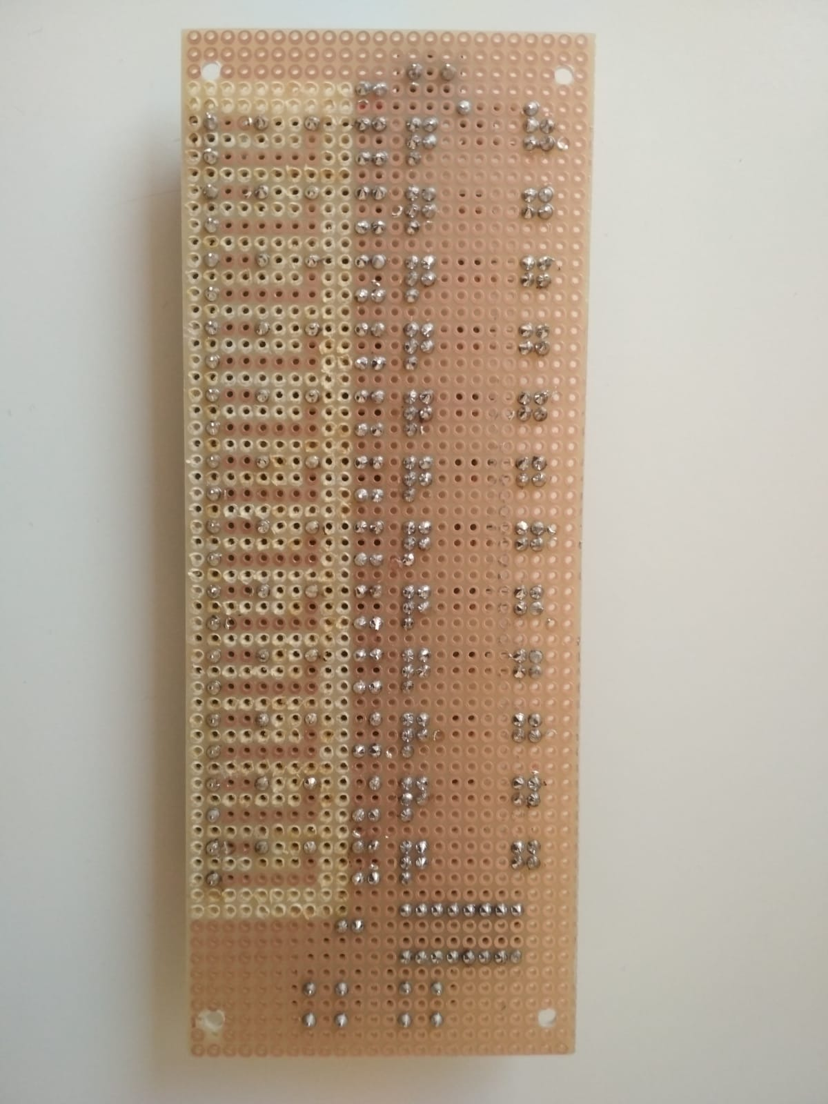
Step 3: remove pads near the high voltage side
(Only for prototyping boards!) After soldering the components, remove the extra pads around the relays and screw terminal blocks, ti improve insulation. This can be done using the soldering iron. Be sure to use a sacrificial tip and not your good one!
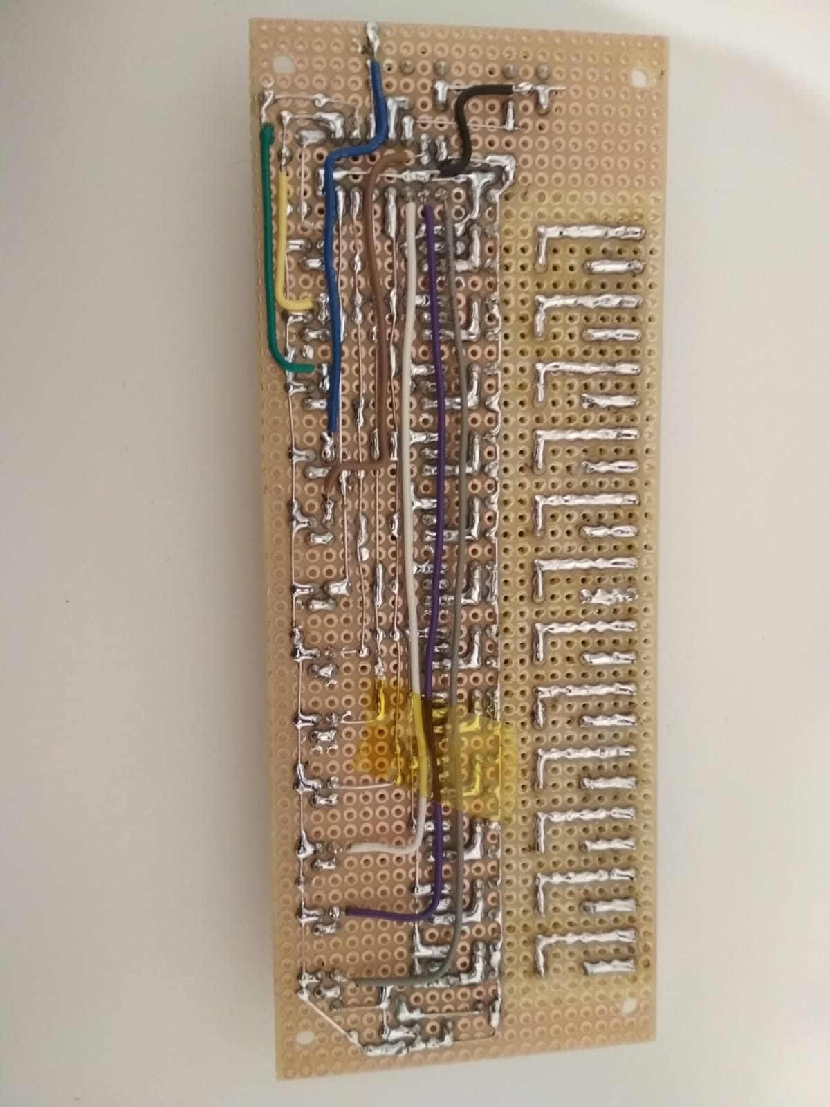
Step 4: create the connections
Make the connections using the wires you cut from the components. Use additional wire when no space is left. 🙂
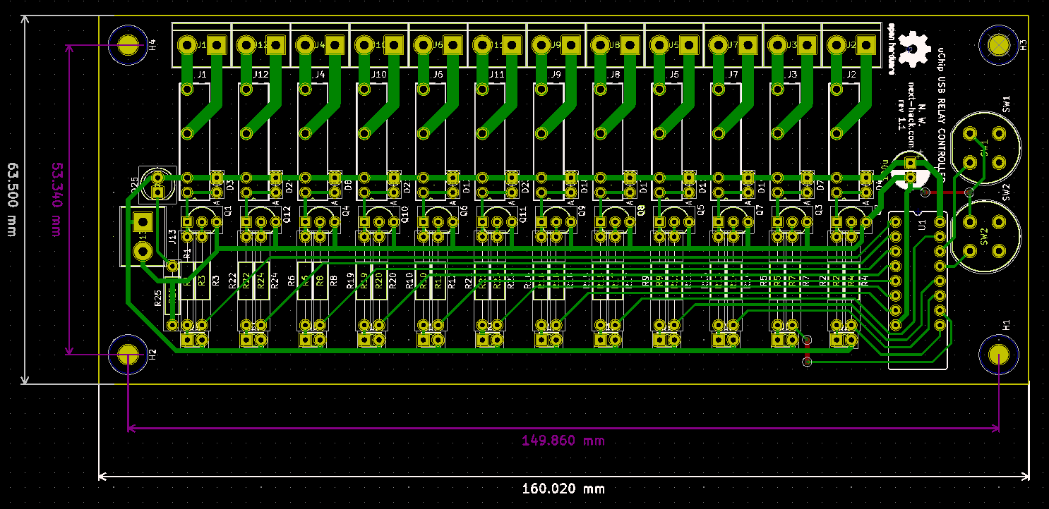
Here is an example KiCAD layout. It will be like the picture below. You can use this as a reference when using the prototyping board.
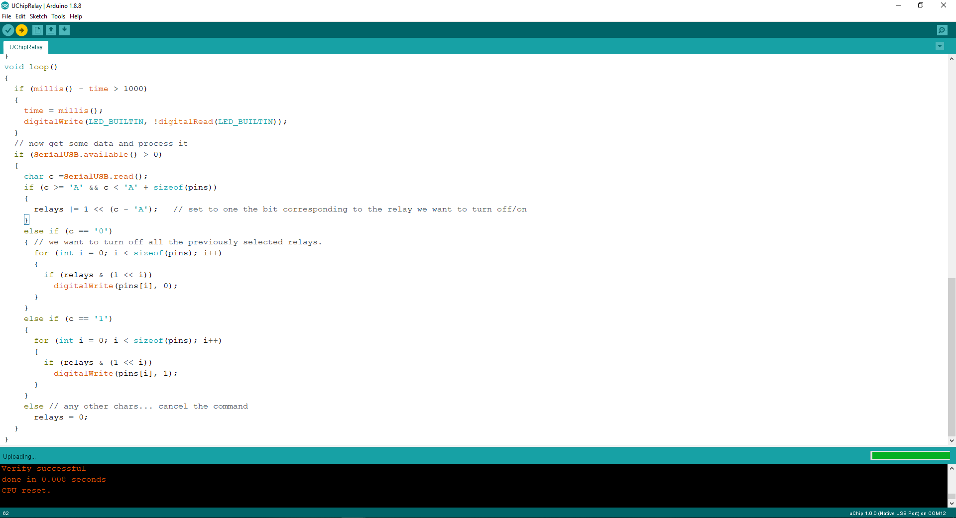
Step 5: upload the sketch
Insert uChip, connect the board with a microUSB cable and program uChip using the sketch provided and Arduino IDE.
Step 6: enjoy!
Use your favourite terminal program (serial monitor, termite, etc.) and write a test string to see if it works. For instance, entering ABCDEFGHIJK1 will cause all LEDs will turn on.