
Introduction
A VGA output might come in handy for a number of applications, such as a terminal/monitor or, why not, a videogame console, which is, by the way, the final goal of this library : – )
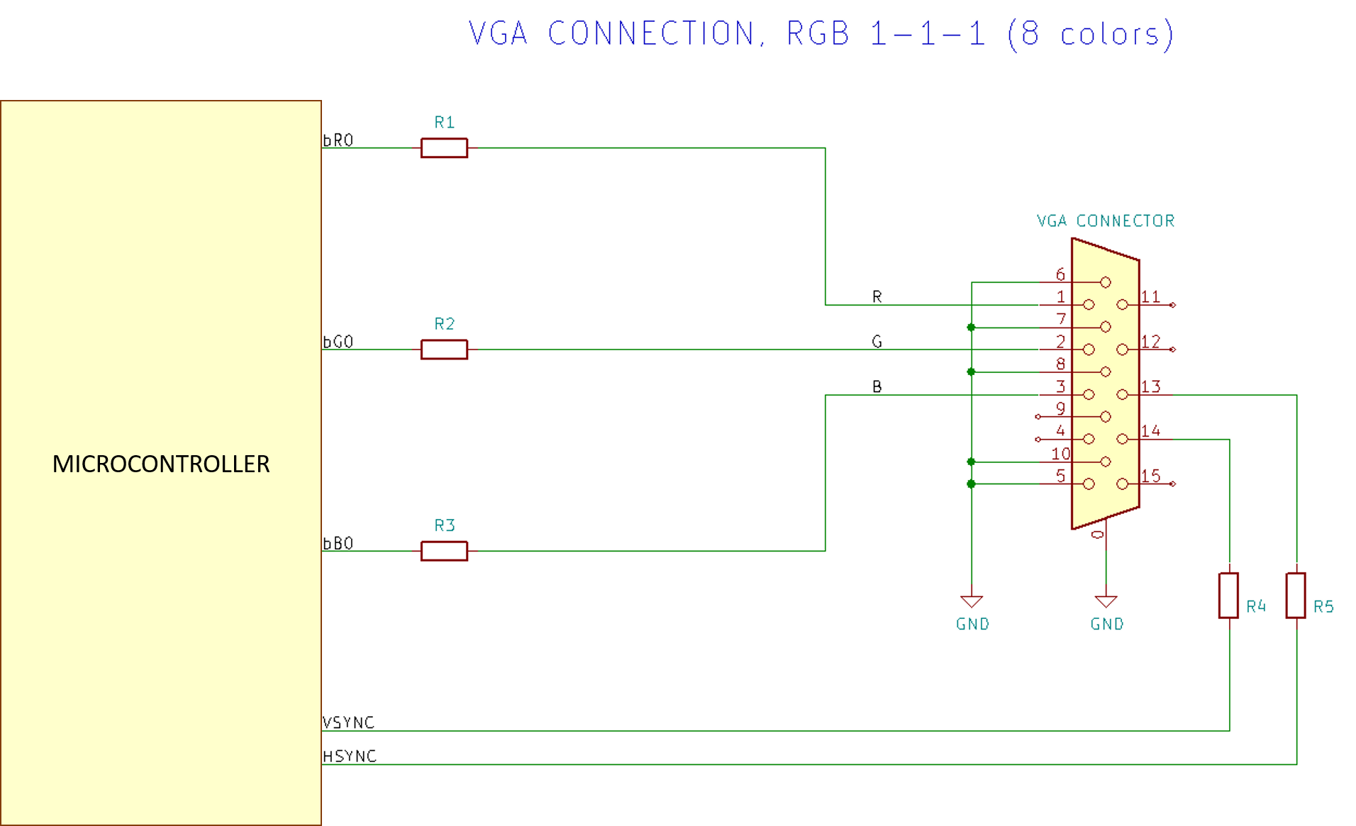
So far, there have already been several successful attempts to generate a VGA signal by software using a “small” microcontroller. In the simplest VGA implementations, there is only one bit per color, i.e, the red, green, and blue signals are connected to one general-purpose input-output (GPIO) pin. This means that the maximum number of colors is 8.
More advanced software-based “controllers” use more than one bit per signal. The most common configurations are 2 bit per each color signal (6 bits per pixel, i.e. 64 colors) or 3, 3, and 2 bits for red, green, and blue respectively (8 bits per pixel, i.e. 256 colors).
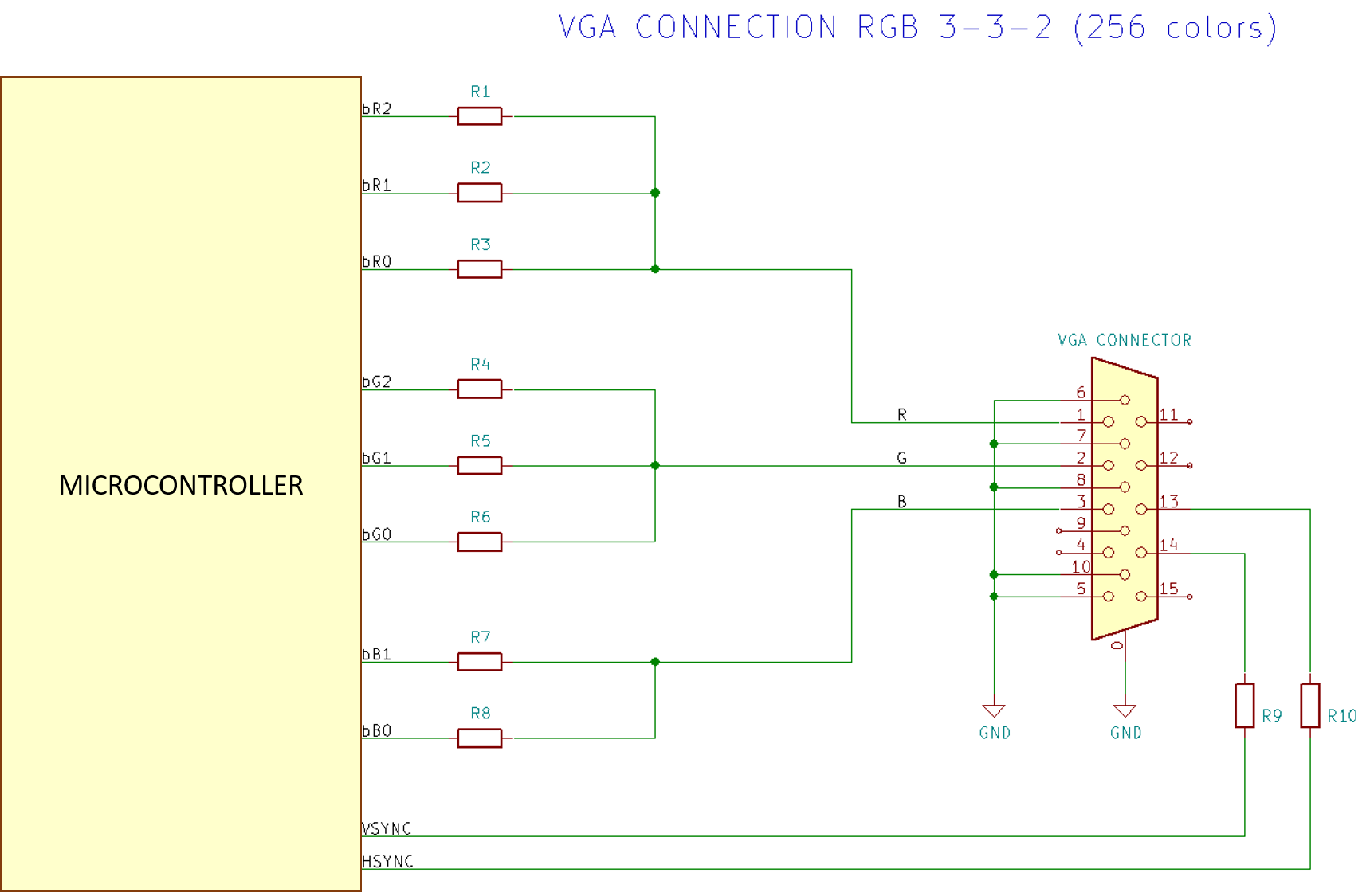
The digital signals are connected to resistor-based digital-to-analog converters (DAC), which allow to convert the 0…3.3V digital signals to the corresponding 0…0.7 V analog values.
While there are some VGA shields and examples for Arduino and, in general, for AVR microcontrollers, on Arduino Zero and ATSAMD21 microcontrollers instead there are none, at least to our knowledge. That’s really a pity, because one could exploit the larger memory and computing power either to perform more advanced tasks (beside showing the VGA image), or to provide better graphics capabilities.
In fact, typical AVR microcontrollers have only few kBs of RAM (between 2 and 8 kB), which strongly limit the maximum number of onscreen colors or the available resolution. Furthermore, the ATSAMD21 features an integrated USB Host, which would allow to use standard USB devices such as a keyboard or a gamepad as input.
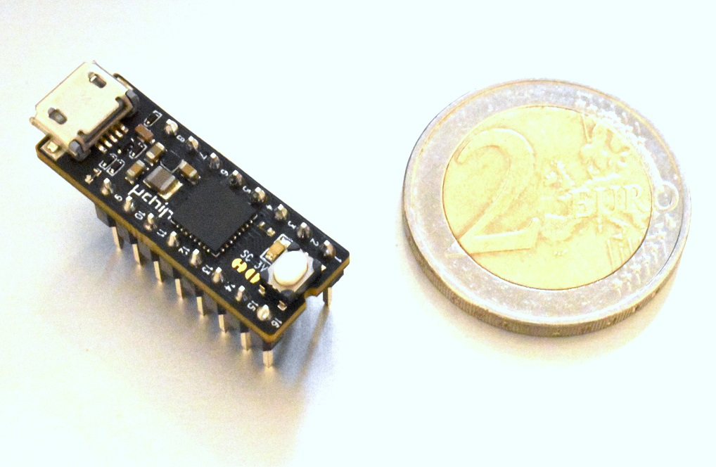
There are many ATSAMD21-based development boards, but many of them are quite bulky. However, the smaller ones, like uChip, feature the 32-pin ATSAMD21E, which has only one contiguous 8-bit port, PA00-PA07 (not all the remaining PA08 to PA31 pins are available). Unluckily, pins PA00 and PA01 are typically used by the 32768 Hz crystal, hence they are not available as an output signal. uChip makes no exception as it was designed to have the best compatibility to the Arduino Zero.
This requires to connect the various red, green, blue signals in non-contiguous pins, meaning that for each pixel we need to perform some on-the-fly calculations or processing.
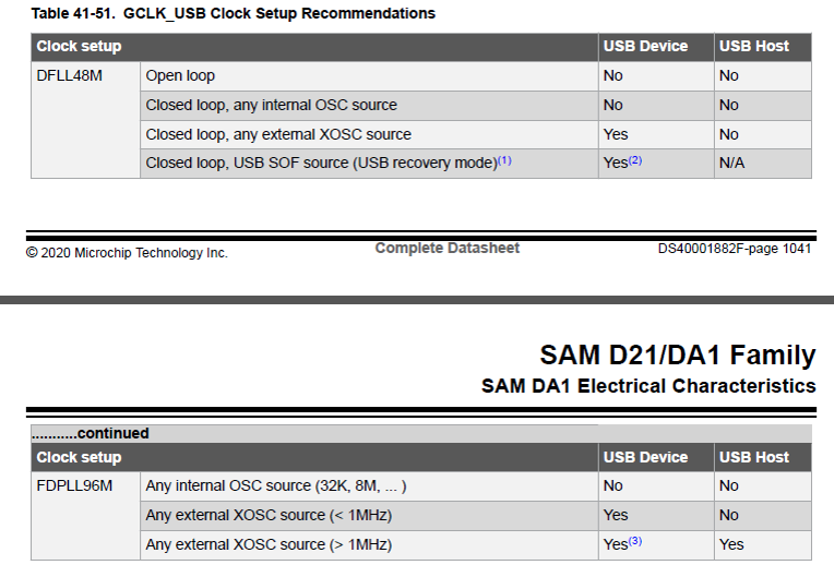
To add insult to the injury, the 32768-Hz crystal oscillator is useless for this project. In fact we verified that the DFLL and DPLL of the ATSAMD21 introduce quite noticeable jitter/instability on the generated waveform if the input clock frequency is low (< 1MHz), therefore the aforementioned oscillator cannot be used as clock source. The amount of introduced jitter is totally unacceptable, as shown by the picture below:

The figure above is a detailed photograph of part of an LCDn SXGA monitor (128×1024 pixels), which shows the effects of jitter produced if the 32k crystal oscillator is fed to the DPLL. Similar results occur using the DFLL. We verified that such jitter is totally absent when using a 4-16 MHz external crystal oscillator. By the way, this might also explain why Microchip suggests using the DPLL with high input clock frequency when using the USB in host mode:
This prevents the straightforward resistor-only implementation of a shield for ATSAMD21-based boards: an external crystal oscillator is required.
All that said, we must also face with the memory limitation. Yes, 32kB is much more with respect to 2 to 8 kB, and 48 MHz is much more than 16-20 MHz. Still we need to remember that we will require some per-pixel on-the-fly processing.
Since there are already some AVR-based applications that allow an 8-bpp palette, we want to have a 256-color space too. We cannot go much higher due to pin and memory limitation. We also want to achieve a QVGA resolution, i.e. 320×240. Actually, we will use only 200 vertical pixels, to save on RAM and to avoid the CPU starvation. After all, nowadays the 16:10 is a much more common format than 4:3, and many monitors allow 4:3 adaption to 16:10.
Timings
How much time do we have? Very little. With a visible horizontal resolution of 320 pixel, at 48MHz we have only 4 CPU clock cycles for each pixel (we assume 525 vertical lines and “about” 60 Hz). Also, note that:
- Flash accesses require 1 wait state, i.e. we would require one more cycle per instruction. The internal SAMD21 cache is a double-edged sword because, on one hand it reduces the average fetch time, on the other, the time required to fetch each instruction is not constant, so the execution time from flash is not deterministic. That’s why we will place our function in RAM (of course, the function is in flash, but it is copied to RAM at startup).
- Data accesses to RAM (LDR instructions) require two clock cycles.
- Branches, if taken, take two clock cycles. For this reason, for the most complex graphics modes we will have to avoid creating a 320-iteration loop: we will create a long sequence of instructions.
- Unlike the AVR, there are no nibble based instructions (like SWAP) on the Cortex M0. These could have been useful for 4-bpp video modes. There are also no immediate-operand AND and OR instructions.
- Even if there are sixteen 32-bit registers, only eight of them (r0-r7) have access to the full instruction set. Some of the registers are special purpose (r13 through r15 like SP, LR and PC), therefore only the remaining r8-r12 high registers are available as general purpose. However, these registers are used by a very limited set of instructions (mainly: BX, CMP and ADD, with no immediate-operand support).
By comparison, there are thirty-two 8-bit registers on the AVR. (Even in this case, many instructions work only with some registers. For instance, there are only three pointer registers – which take six 8-bit registers – and immediate-operand instructions mostly work with r16-31 only). The availability of 8- instead of 32-bit registers is a penalty when doing general data processing, however they would have been very useful for VGA signal generation, as the data width is 8-bit. In this sense, having 4 bytes stored on a single register is quite painful, when it comes to quickly separate them. Yes, there is the UXTB (unsigned byte extend) for the least significant byte, and LSR (logical shift right) for the most significant byte. However, we cannot extract with a single instruction the central bytes: we need to use REV16, so that the central bytes can be later separated with UXTB and LSR. On the bright side, four pixels can be loaded at once, with only a 2-cycle instruction.
Luckily enough, the ATSAMD21 feature a local bus for the I/O ports, allowing for a single-cycle access. This means that for each pixel we have on average 3 cycles left. In these three average cycles per pixel we must perform all the decoding or pre-processing required to calculate the actual value to write to the port.
The VGA synchronization signals are generated by two ATSAMD21 timers, so no CPU intervention is required. The VGA signal generation routine is entered by an interrupt having the second highest priority (i.e. 1), generated by the horizontal sync timer. In that interrupt, we check which line we are currently drawing, and if it is in the visible area, the actual drawing procedure is executed.
Interrupts might have some variable latency therefore, to ensure a precise start-of-line, another timer is configured. This timer generates an event at a fixed delay with respect to the horizontal sync signal. The event, in turn, generates the higher priority interrupt (i.e. numerically 0). If we did not disable interrupts, once the event is triggered, the CPU would jump to the relative interrupt handler: we do not want this, therefore we disable the interrupts as soon as we enter the first handler. Instead, at a certain point, i.e. right before where the actual line drawing should occur, we put a “Wait For Interrupt” instruction. I.e. the CPU will sit there, until the event is triggered. Such solution allows for deterministic and very fast interrupt detection, therefore the lines are drawn at the same horizontal position, which can be adjusted by the delay with which we generate the event.
The current state of the art
So far, we have squeezed out the following operating modes.
Bitmapped mode
The first one is a bitmapped mode. A bitmapped mode is when one pixel is mapped to one or more bits on memory.
Let’s make some calculations: A 320×200 screen has 64k pixels. This means that we cannot use 8 bits per pixel, as we have no enough memory. Even 4 bits per pixel would leave too few bytes on our microcontroller, especially if USB has to be used.
This means that either we need to lower the resolution, or we need to reduce the number of colors.
In our bitmapped mode, we have 2 bits per pixels. This means that each pixel can assume 4 different values. Each value is mapped – via an array called Palette – to a specific user selectable color. In this way we have 4 colors onscreen.
But, we have a couple of tricks, which might come in handy. In fact, the palette is not fixed, but instead is optionally indexed on an 8-pixel basis, allowing almost to fully exploit the 256-color palette (of course with some limitations).
Another trick is that, to save on memory accesses, we compute two pixels (4 bits) at once. By carefully choosing the palette, one can halve the horizontal resolution, and join two pixels. This has the effect of actually having a resolution of 160×200, with 4 bits per pixel (16 color). Again, the palette can be changed every eight pixels.
Furthermore, one can choose the palette so that two colors work in “high resolution mode” – 320×200 – and the other remaining colors work as usual, 160×200 pixel. This is useful if you need to write text and display some color graphics.
The features are as follows:
- Up to 320×200 pixels.
- The palette is 4 colors per pixel (or 16/32 per double-pixel). The palette can be changed every eight horizontal pixels.
- The palette determines the actual horizontal pixel size (1 or 2 QVGA pixels).
- No scroll, no sprites, for now.
- Small RAM footprint of the VGA-signal generation function, because it uses a loop (unlike tile mode1 and 2, see below)
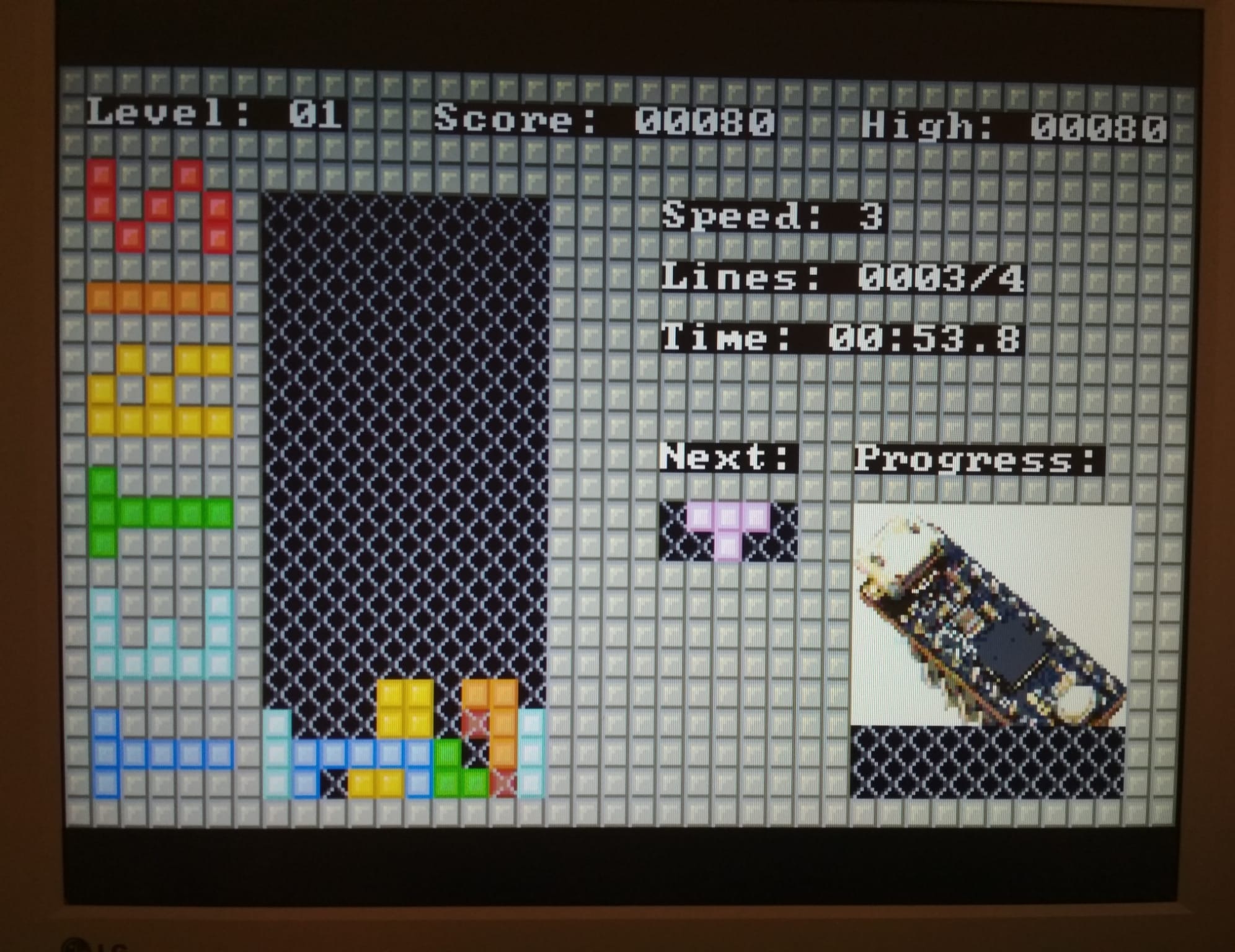
Below you find a preview of this bitmapped mode.
Tile Mode 1
As we saw in the handheld platform game article, 2D games usually are tile based, i.e. they repeat the same few graphics elements (tiles), while they superimpose sprites for bonuses, enemies, player, etc.
We can do the same thing also for the VGA. With respect to the hand held platform, we need to radically change the way the image is created. In fact, instead of creating the image on per horizontal-slice basis, we must have the image “ready” before each frame begins. For “ready” of course we do not mean that the full bitmap image is already rendered on memory: we already know that this is impossible, due to memory limitation. We simply need that the image can be outputted with “minimal” per pixel processing.
For this reason, we store in a table (the vram, i.e. video ram) the references[1] to the tiles to be drawn on screen.
The features are as follows:
- 320 x 200 tiled mode. Each tile is 8 by 8 pixels. The vram size is configurable, but the minimum is 40 x 25 entries, each one storing 2 bytes, which Is the lower part of the tile address (the higher part is 0x20000000, being all the tiles in RAM).
- Up to 400 different tiles on-screen (actual number of tiles depends on how much ram is available).
- X and Y smooth scroll.
- Optional per-line and per-tile X scrolll, allowing to produce some nice effects, like water deformation or parallax.
- Optional fixed top or bottom static zone to display score, or other information.
- Optional row remapping, allowing for instance split screen, or other effects like mirroring or upside down display (e.g. as a temporary screen-reversal malus like in Apidya on the Amiga).
- 256-color palette for tiles and sprites[2].
- “Unlimited” number of sprites. Actual sprite number depends on how many free tiles are available for the sprites, the sprite size, position and alignment. The sprite drawing routine automatically handles “any” size of sprite (i.e. no needs of splitting larger sprites in smaller ones).
- Sprite rotation (90, 180, 270), horizontal-vertical mirror and x-y swap.
- Different sprite handling positions.
- Custom sprite/background blend modes for special effects such as lights, semitransparent explosions, etc.
- Tiles on screen must reside in ram. However, you can copy tiles from the Flash to the ram at very high speed during the game, so animated tiles are easy to implement.
- Optional sprite and tile priority.
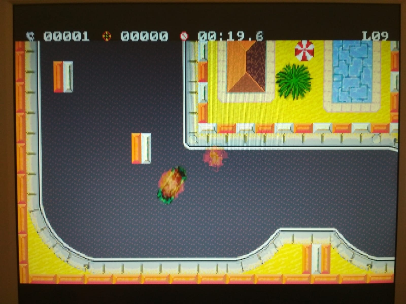
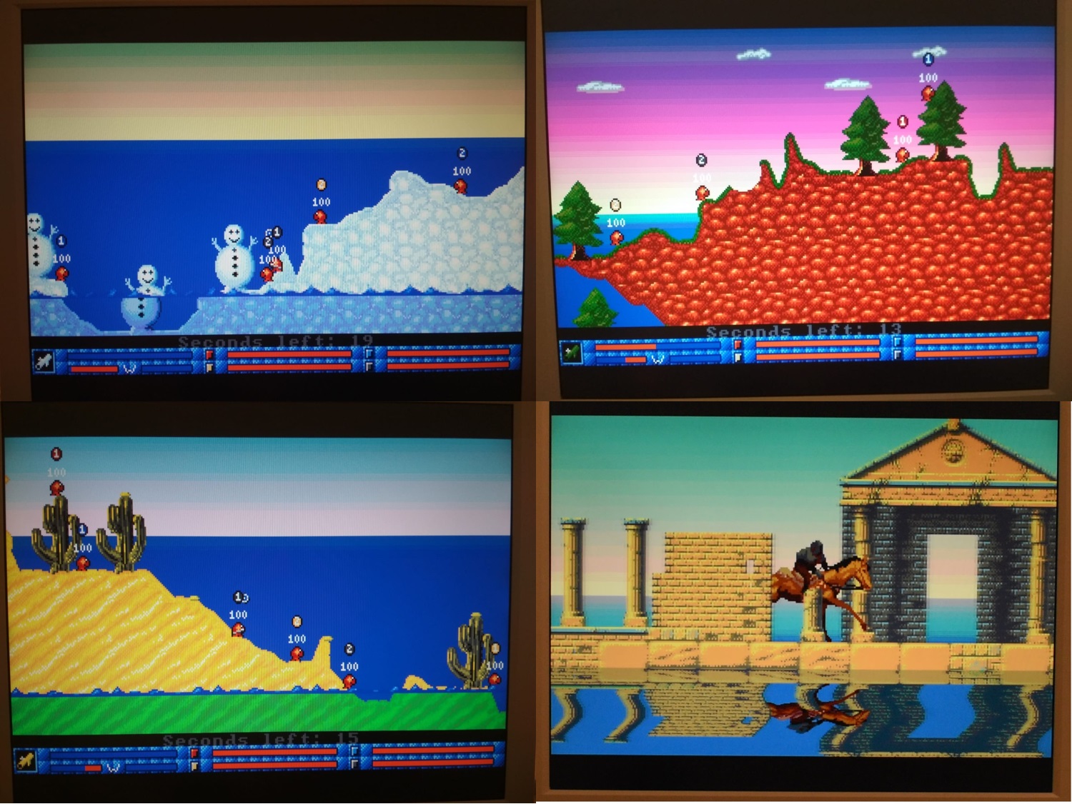
This is a preview of the tile mode 1.
Tile Mode 2
It is the same of Tile Mode 1, but it uses a 16-color remappable palette (allowing up-to 256 onscreen colors). This has the following advantages:
- The tile occupation is 32 bytes instead of 64, therefore the maximum number of tiles is almost doubled (around 700).
- Per row color changing palette engine, that allows on per low-res (200) or high-res (400) line basis:
- To switch to another palette, i.e. changing all the 16 colors in a single row (useful for water effect)
- To change a selected color of a palette, to any color value (useful for creating background shades).
The color changing engine however requires 1kB of RAM per additional palette.
Tile mode 2 has one disadvantage: it does not allow 90° and 270° sprite-rotation. Only vertical and horizontal mirroring are supported for now. It also does not support custom sprite-background blending for now.
Furthermore Tile Mode 2 also allows high-res (400-lines) row remapping (this feature will be implemented also for tile mode 1 in the future, as it is currently low res – QVGA- only).
Tile Mode Boot
This mode has been developed to be used for the bootloader only, with the exclusive goal of having the smallest flash memory footprint, while providing 256 onscreen colors, for the game preview. To achieve this, tiles must be stored in RAM in a 128-byte uncompressed format (i.e. signals ready to be outputted).
This mode also supports vertical row remapping.
Notes for all the modes
Actually, with minor modifications all the video mode could support up to 320×240 or even 320×400/320×480 pixels. However when using 400/480 lines, the pixels will have a 1:2 aspect ratio. Furthermore, using 240/480 lines, there will be very few time left for the CPU! More CPU cycles can be achieved by drawing only the odd or only the even scanlines, emulating the classic CRT effect. However during these spare lines, the CPU should not draw sprites, otherwise flickering might occur.
There is an additional mode, which is work-in-progress, and can also work together with the previous tiled and bitmapped modes, but requires an external 74AHC245, the SPI Mode.
This mode is totally hardware-driven, and it leaves plenty of time to the CPU, as almost no intervention is required.
It features these specs:
- 2 colors, of which one is black.
- Works either as standalone or with all the previous modes.
- Up to 640 pixels per line.
- Up to 480 vertical lines.
This is best suited for text modes, or to display score or other useful things.
Conclusion
In the next
posts we will talk more specifically about uSVC, uChip Simple VGA Console, how
modes work, and, more importantly, how to build your own games!
[1] We actually store the lower part (16 bit) of the address of the tiles to be drawn. The higher part is fixed to 0x2000, which points to the RAM region.
[2] Actuallly sprites have 255 colors (black is transparent).
Is there any actual code I can look at? I am very curious about the idea of software generating VGA on the SAMD21, but I have read all three articles and there doesn’t seem to be any actual code
Hi there!
The code will be released in the Github repository next thursday as update of the CS campaign (https://www.crowdsupply.com/itaca-innovation/usvc) ! Stay tuned!
Hi, I have published the template project. There you’ll find also the kernel, where actually the vga signal generation is handled. https://next-hack.com/index.php/2020/10/28/usvc-kernel-source-code-and-template-project-released-and-a-crowdsupply-campaign/