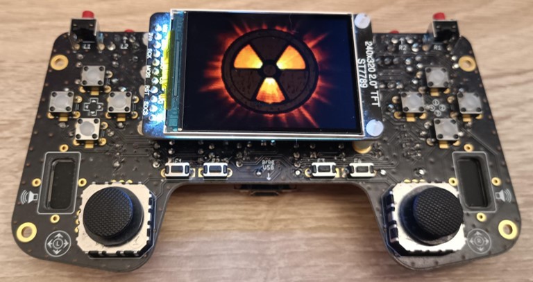
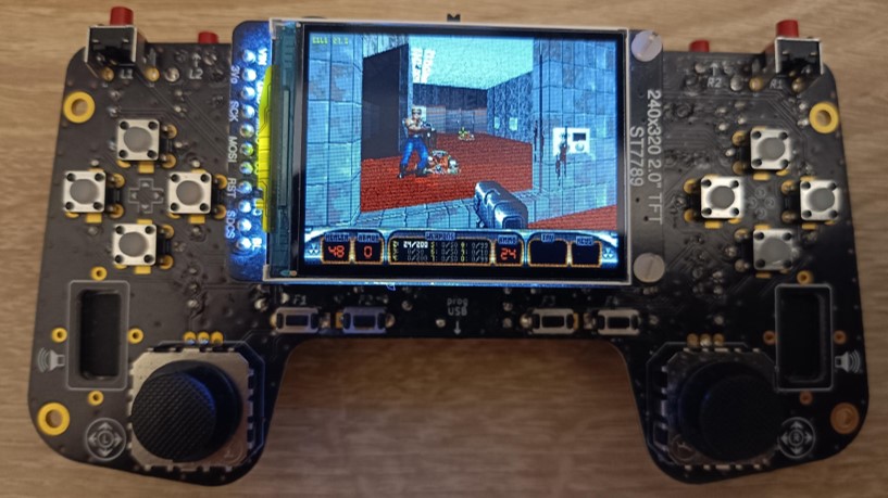
“It’s time to kick ass and chew bubble gum! And I’m all out of gums.”
tl;dr;
– The source is here: https://github.com/next-hack/MGM240_DukeNukem3D.
– Hardware design files (remember to use 32 MB flash ICs to play Atomic Edition!): https://github.com/next-hack/TheGamepadDesignFiles
Introduction
Last year, we published the port of Quake to the Arduino Nano Matter Board and in general to the Silicon Labs EFR32MG24-series microcontrollers. That port was initially supporting only the shareware version of Quake. Despite we promised ourselves that our job was concluded, just one month later we published an upgrade, which not only supported the full retail version, but also it increased the speed by some fps.
But in the pipeline, we had already another game…
The true story behind the scenes
In the Quake article, we did not want to spoil the fact that we were already working on another project, so we left out some background details. We would like to clarify those now.
As we wrote, after we realized that Quake was “ported” to the GBA we concluded that we should have ported it to the Arduino Nano Matter as well. However, we did not mention that there was another big candidate we wanted to work on. And that candidate was Duke Nukem 3D.
At that point we had one big dilemma: should we port Quake or Duke Nukem 3D first?
Before telling why we finally decided to go for Quake first, let us spend few words on Duke Nukem 3D.
Duke Nukem 3D was released in 1996, few months before Quake and, despite being in several aspects technically inferior, it was, at least in our opinion, much more fun to play. In particular, the weapons, despite being sprites, were much better looking with respect to Quake. The shotgun in Quake did not look like a shotgun. The rocket launcher in Quake bore an unfortunate resemblance to something best left to the imagination — which is precisely why we’ll refrain from elaborating further… And yes, while we see the effort of introducing “cool” weapons in Quake, like the nailgun or lighting gun, their appeal pales against those present in DN3D: the shrinker, the freezer, or even the remotely controlled pipe bombs, just to mention a few.
Also, in DN3D you could interact with the environment in a way never seen before. You could destroy many things, including some walls or even demolish entire buildings. You could enter a metro station and take the trains. These features were possible thanks to some unique features in the BUILD engine, which allowed things like movable sectors, or changeable walls.
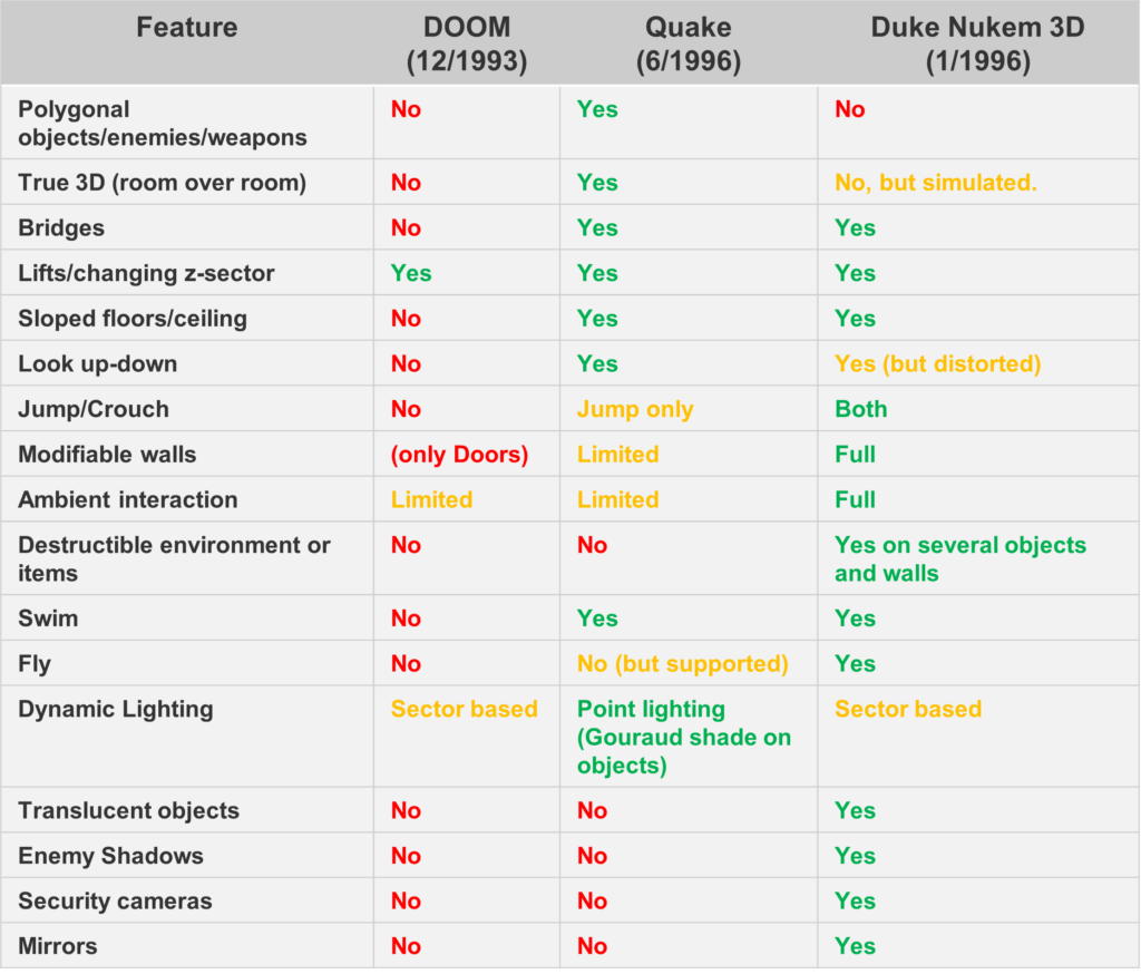
Beside the aforementioned features, Duke Nukem 3D, still had other technical advancements with respect to DOOM, including bridges, sloped floor/ceilings, the possibility of ducking, jumping, looking up-down (sideway as well), screen tilting, partially transparent sprites, scripting engine, security cameras, mirrors and audio reverb.
There were, however, three things that pushed us into trying to port Quake first.
- Quake is more advanced graphically and it was a radical change with respect the plethora of Doom-like engines (despite DN3D and Doom have a different engine, one based on passages other on BSP, they are both considered as 2.5D as opposed to true-3D engines). This was a high-risk high-reward project: the success was uncertain, but the result would have been much more impressive than porting DN3D.
- A very constrained Quake was already ported to the GBA (albeit with tons of limitations, due to the very limited CPU), so it was anyway not totally unfeasible a-priory.
- The DN3D code base… Auch.
The code base (part 1)
When in 2023 we started looking at Quake and DN3D code bases, we found immediately the official WinQuake source code, and also its SDL version, which allowed for easy development on a modern PC. That code also had, together with the original optimized assembly drawing routines, a portable C version. Instead, for DN3D we mostly found too many modern variants. Besides some bugfixes, these modern ports introduced new features that were not present in the original game, at the expense of memory: it would have taken us more time to remove them to have the game fit in our memory. On the other side, unlike Quake, the original DN3D code had a lot of x86 assembly code, which would have been very hard to port. So, we looked if there was something like Chocolate Doom, but… not Doom, just DN3D. And guess what, there was!
But, after a first glance reading of the article (https://fabiensanglard.net/duke3d/) from Fabien Sanglard, we were left feeling quite a little bit discouraged:
- The project consists of two modules that must be compiled separately—one for the BUILD engine (developed by Ken Silverman) and one for the game code (developed by Apogee/3D Realms). Managing two separate codebases would have been a nightmare in terms of optimization and debugging.
- Sanglard’s writeup made it clear that the code was difficult to read and maintain. As we’ll discuss later, that was actually an understatement. In hindsight, we’re glad we chose to go with Quake. Even though Duke Nukem 3D was truly the one closest to our hearts.
As a side note, unfortunately, we just bookmarked Fabien Sanglards’s website, without browsing for other articles: it would have been very helpful reading his Quake source review, as it would have saved many hours of analysis, before starting our Quake port.
Coming back to DN3D, in June 2024 we chose Chocolate DN3D, because:
- It was guaranteed to work on a modern Windows, thanks to its SDL support.
- It was commented by Fabien Sanglard.
- It was cleaned up a little bit, at least up to a certain point.
- It was very close to the original source. The only changes were mostly the conversion between assembly to C drawing routines, some filesystem supporting code and some changes in the audio-related code.
After cloning the repo, we created a Code::blocks project and modified few sources so that both the BUILD engine and the full game sources would compile in the same project. It was time to start a new challenge!
Notably, we used the 32-bit version of minGW, so that we have 4-byte pointer, and not 8. This is important because in the Windows application we emulate the internal flash of the MCU, to understand how much space is left. If we had to use pointers, it is better to have the same size, otherwise the Windows application would overestimate flash usage.
A new Challenge
The new challenge follows closely what we have done in the past. In particular, we should support the Silicon Labs MGM240P and MGM240S modules (present in the Sparkfun Thing Plus Matter and Arduino Nano Matter boards) with:
- No external RAM, no electronics that will offload the main MCU.
- Admitted any amount of external flash.
- No graphics detail reduction (except from screen tilting, see later).
- Sound support, with the usual 11025 Hz 8-bit stereo.
- We can develop any script needed to modify the GRP file so that it is easier to handle by the port, provided it does not change the level complexity or graphics details.
- Any amount of overclock (unless stability is affected) is admitted.
- Full save game support, like we did for Quake.
We realize that Quake is much more complex with respect to DN3D, so these additional constraints were added:
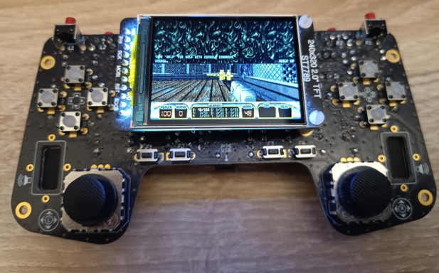
- Support for the full display resolution (320×240 pixel) instead of just 320×200 as we did for Quake. The constraint about resolution includes the status bar.
- Music support with OPL2 chip emulation.
- Multiplayer support over radio, with at least 4 players. The original game supported 8 players, but this would require few more kB and it is very unlikely that 8 people would join and play a multiplayer game on The Gamepad. In this sense, it would be a waste of effort on our side.
- The audio engine shall support the original reverb effect.
- Full features support like mirrors, security cameras, screen tilting (see later).
- Support for animations (like logo, end of game, etc).
- Frame rate always above 20 fps if overclock is used.
- The full game shall be playable (i.e. not just shareware).
The following are constraint relaxation:
- The audio sample rate can be 11025 Hz 8 bit, despite some effects have a sample rate of 22ksps and 16 bits per sample (like the shotgun sound).
- The reverb included in the Chocolate Duke Nukem 3D is much more sophisticated than the original one. It included a more complex processing simulating more than one reverb path, muffling, and the vibration/resonance of walls induced by the sound. This was added later in xDuke port, on which Chocolate Duke Nukem 3D is based. This would have required much more RAM, so we decided to go with the original one, much simpler.
- For screen tilting, as it is quite rarely used (when the player dies, or when turning the head left or right), the detail can be lower. This is a must as the screen tilting requires a big temporary buffer.
The code base (part 2. A rant)
Despite the tremendous effort that Fabien Sanglard put into cleaning up (an almost impossible task) and commenting the code, it remains very difficult to read and maintain. We also looked at the original code and were genuinely surprised that the developers managed to produce such a great game despite working with such an unwieldy codebase. It almost feels as if both the Build engine and the game sources were run through a code obfuscator before being released.
- Bad variable naming. Do you think that xvel, yvel and zvel are the x, y, z components of the velocity, right? Well, sometimes they do, but not always. We understand this was likely done to save memory by reusing fields for other purposes when velocity data was not needed, rather than adding separate fields for different purposes. Using unions could have improved understandability significantly, still reducing memory usage.
- Very bad coding practices. What does one programmer think when he sees this?

Of course, you might say, they are checking if n is equal to the constant SLT! Well, read this instead, in game.c!
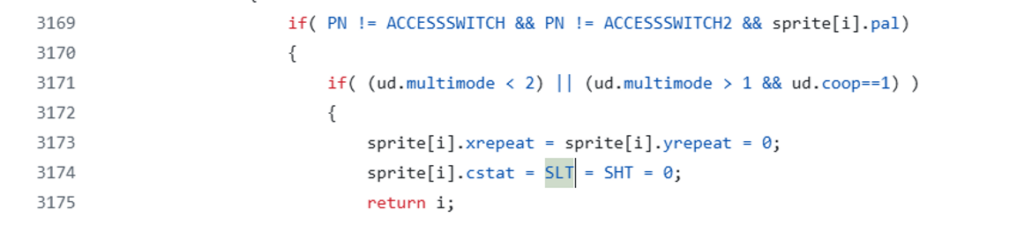
What? How the hell can even compile this? Let us check what SLT actually is in duke3d.h…
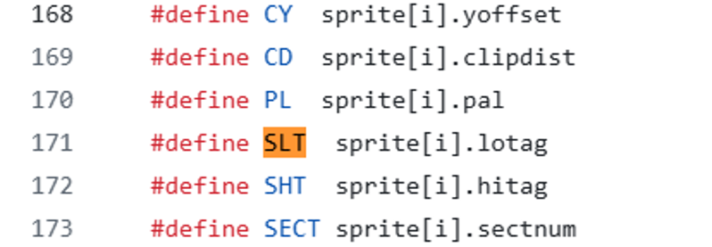
This is a very awful bad coding practice. All these symbols should have been defined as macro, to indicate their dependence on the variable “i”. Like “#define SLT(i) sprite[i].lotag”.
- Other example of bad
#defineusage is this.

- There are many global arrays. Many of them should have been in stack instead. Sanglard took the effort of putting some of them on stack, but we later realized that many more could have been put there.
- In other cases, the same array is reused, which is something we did also for porting Quake However, this is hardly documented and creates a lot of confusion (and crashes, when trying to trim the array size, without knowing the array is used somewhere else).
- Very few comments were present on the code, even for very complex functions (beside Fabien’s ones).
- Huge switch-case statements, with a lot of magic numbers (i.e. number explicitly written, instead of a symbol which tells what t corresponds to). How could the developer(s) even track of everything ?
- Magic numbers are used also all throughout the game code, for which you can’t really tell what a value means.
- The source is full of redundant code, with a lot of duplicated parts.
Our Port: the extent of code modification
Many game ports require only minor modifications to adapt to different hardware or operating systems. Typically, these changes affect the code that interfaces with input devices (keyboard, mouse, gamepad), output systems (audio and video), and the filesystem. The bulk of the code, however, remains unchanged.
This happens, for instance, when the target system has sufficient memory and processing power, so no optimization is needed—you simply need to support a different machine. Such ports are straightforward tasks, not real challenges. And frankly, we find them rather boring as well.
This is not one of those simple ports. Almost every function has been modified—or in some cases, completely rewritten. In the following sections, we’ll cite only a few examples, as discussing everything would take ages. Interested readers can use a tool like WinMerge or diff to appreciate the extent of the porting effort.
Memory optimizations
As we did in Quake and Doom, the first way to reduce RAM usage is to put/leave all the constant data in Flash. In particular, data that is sequentially accessed, such as sounds and wall textures, can stay in external flash. Instead, constant data that is not accessed sequentially, like map data, tables and large floor/ceiling textures, is stored/cached/copied to the internal flash.
Unfortunately, with DN3D, determining what is constant and what is not is extremely difficult. In fact, in Quake and Doom, there are many easy-to-spot large structures that, once loaded to RAM, are not modified again, at least before a new level starts. These are the best candidates for internal flash storage. In other cases, in Doom and Quake, some structures contained both constant and non-constant data, but these could be easily detected and separated. So, we split some structures in two parts, one going to flash, and one staying in RAM.
In DN3D, this is not so easy, because almost everything can change, a priori. For instance, entire sectors can move, walls can change coordinates, etc., something that in Doom and Quake was not possible (do not confuse the ability of the DN3D engine to move walls/sector with the limited sector-height changing in DOOM or movable brush-models in Quake).
Luckily, we figured out that there is still some data, which is always constant (on per-level basis) in some structures like sectortype and walltype. For instance, in a walltype structure, the fields nextwall and nextsectors are constant. Similarly, in a sector, the first wall index, and the number of walls in the sector will never change during one level.

Therefore, we separated the constant data from potentially variable data, creating in general 3 structures for each object:
- disk structure type. E.g. disk_walltype. This is the original structure, and it has been renamed to “disk_” because we will be loading the information from the GRP file in the “disk” (in the Windows application) or external flash (in the target device).
- const structure type. E.g. const_walltype. This contains all the fields that will always remain constant. This data is copied to internal flash.
- The RAM structure, which contains only those fields that may change.
Five memory allocators
Still, the above-mentioned solution alone is not enough. For instance, if we know that there might be up to 5200 walls in a map, in theory we should statically allocate an array with 5200 “RAM walls” structures. However, this would occupy a very large RAM amount (in the order of many tens kB ). Fortunately, even if potentially all the sectors and wall can change, actually only “few” of them will do. Therefore, we can use a rudimentary dynamic allocator and have all the fields accessed using getters and setters.
However:
- There are 4 main objects in DN3D, and these need different handling to get the best optimization: sectortype, walltype, spritetype and weaponhittype.
- From the code, it is incredibly difficult for us (unlike what happens in Doom and Quake) to understand if something (e.g. a wall) can change or not. For instance, in Doom some walls had a “special” flag, to indicate that one of their properties could change.
The general idea we took was to statically declare for each object an array of RAM structures with a smaller number of elements (the particular value being found by profiling/playing the game). Now, instead of accessing directly the data, like walls[i].x, we created setters and getters, so that one can retrieve the same data by calling getWall(i)->x or getWall_x(i). These setters and getters will use an array of indexes (e.g. rammwallidx), to check whenever the object was modified. If it was modified (non-zero index), then the RAM structure is used. If it was not modified (index is zero), the structure in flash is used instead. When trying to set a property, the setter will first check if the object was already modified, and in such case it will access the object in RAM and modify the property accordingly. Otherwise, it will check if the new property value differs from what is in flash. If this still is not the case, a new object in RAM is allocated from the array, and its index is copied to the array of indexes.
The following picture shows how an example of what happens when changing the x coordinate of the wall number 4 to the new value 100. Red arrows are actions taken.
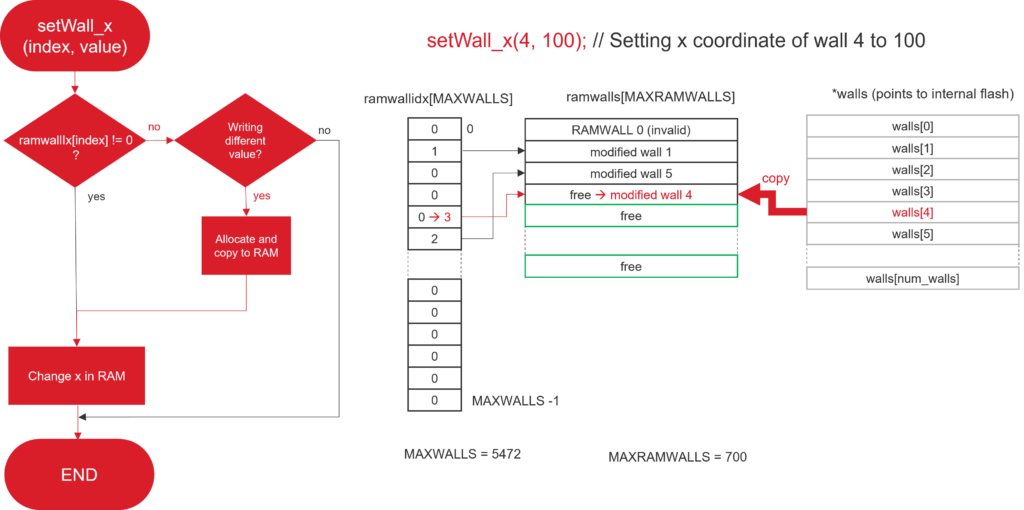
The array of indexes is statically allocated, and the number of elements was found by analyzing all the levels automatically, and printing out the limits.
The above description is very faithful to what we have done for sectors and walls.
Spritetypes and hittypes are very different beasts (note that hittypes contain basically more information about sprites) and these are very dynamic objects. In fact, in DN3D, walls and sectors are not created at runtime: if a sector or wall changes an element of the array in RAM is reserved for them, but it is never freed unless the level changes. Instead, sprites are created and destroyed during the same level, so we must not only provide a way to allocate a sprite in RAM, but also a way to deallocate it, without clearing the whole array.
Notably, each level contains hundreds of sprites that remain static. These include wall or floor/ceiling decals—sprites painted onto surfaces that never change. This approach allowed the creators to reduce the number of textures while still adding visual variety.
Since these sprites are static, reserving RAM for them would be a significant waste of memory, so they are stored in flash. Unfortunately, as mentioned earlier, we cannot easily determine which sprites will change (unlike static objects in Doom), so we store all sprites—and their hittypes—in internal flash by default. When needed, we allocate a slot in the RAM array. Once the sprite is deleted, that slot is released.
Now let’s discuss about hittypes. These store additional game-related data about the sprites, but we found that many of their parameters are rarely used, i.e. they are zero. For this reason, hittypes have a 2-level allocators. One is to allocate the hittype itself, and another to allocate additional data for up to 6 parameters (e.g. in the original source, such parameters were stored in the “tempdata[6]” field).
Still, not all sprites were created equal. Some sprites are important as they are fundamental for the game logic. Other sprites are just cosmetic/ancillary. For instance, we might cite the bullet holes or blood splats on the walls: if one is missing, it will be very hard to notice it has been deleted.
Therefore, if we run out of sprites/hittypes, we will free one of such ancillary sprites. In other words, we created also a rudimentary garbage collector.
Walls and Sectors, the whole story
In the original walltype and sectortype structures, there are fields that will change on too many elements. For instance, the shade propertiy will change on a very large number of walls, because many rooms have lights, which can be turned on or off. This would have required to statically allocate an incredible large amount of ramwalls. Instead, we have separated such properties and put in them separated arrays in RAM. These arrays have a number of elements corresponding to the worst case scenario we found by analyzing all the map data. There are many thousands of walls, so such array is many thousands of bytes. However, if the shade property was included in the ramwall structure, then the ramwall array would have occupied about 100 kB of RAM.
Similarly, we found that there are some data that can either assume two values. In this case we used an array of bitfield to indicate which value is used.
Why not using a single Z-zone-like allocator?
Great question, we are glad you asked it!
We chose not to use a single Z-zone-like (or worse, malloc-based) allocator for several reasons:
- Memory Control
By using statically allocated arrays—one per element type—we maintain direct control over how much RAM is dedicated to each kind of element. With a single dynamic allocator, we would need to run the game to determine actual RAM usage per type. While we still need to run the game to verify whether we’ve allocated enough space for dynamically allocated RAM walls, sectors, sprites, etc., once we’ve determined the correct limit for one type (e.g., the maximum number of RAM walls), we can move on to the next (e.g., RAM sectors). - Fragmentation
Our objects vary significantly in size. For example, hittype tempdata structures can be as small as 4 bytes, while others may be 20–32 bytes or more. A freed tempdata block would only be useful for allocating another tempdata. Yes, this issue existed in Doom and Quake as well, but here we are operating under tighter constraints. - Overhead
Even with memory pools, each object incurs a 1-byte overhead. Without pools, the overhead rises to 4 bytes due to memory block metadata. Additionally, we must store the object’s address—16 bits if using short addresses like in Doom and Quake. In contrast, static arrays allow us to use indexes, which can be reduced to 8 bits if we only need 256 elements. Static arrays do have some overhead: we need a bitfield array to track allocation status, but this only costs 1 bit per element—eight times less than a byte. - Alignment
Allocators typically return 4-byte aligned objects. With static arrays, we can use packed structures of arbitrary length. While it’s possible to build an allocator that supports arbitrary alignment, doing so would prevent us from using short addresses. - Predictability of Usage Patterns
Dynamic memory would be more beneficial if the distribution of memory usage among walls, sectors, sprites, and hittypes varied significantly, while the total remained constant. For example, if the largest levels (with many changing walls and sectors) had few sprites, and smaller levels had many sprites. However, in our case, the most complex levels tend to have both the highest number of dynamic walls/sectors and the most sprites. In contrast, a single dynamic allocator worked well in our Quake port, where we had 22 entity types with varying sizes and highly variable usage patterns across levels.
Trimming arrays and data type sizes
As in Doom and Quake, the developers declared arrays with a number of elements often much larger than what was actually needed for the stock levels. This approach allowed for future expansion—more complex maps with additional objects could be added later via expansion packs, mods, or community contributions.
However, the goal of this port is to support only the stock maps of DN3D, so declaring too large arrays would simply waste memory. Additionally, the source code of Chocolate DN3D used significantly higher limits than the original DN3D code, likely due to enhancements inherited from xDuke. These limits have been reverted to match those of the original Duke Nukem 3D.
As in Quake, the game contains two classes of arrays:
- Deterministic Arrays
These arrays have sizes that can be determined based on the specific map. For example, the maximum number of walls, sectors, and similar elements can be established by analyzing all the maps. These values remain constant during gameplay—for instance, the number of walls in a level does not change. - Non-Deterministic Arrays
These arrays contain elements whose count cannot be determined in advance by analyzing the maps. A prime example is sprites. While we can determine the initial number of sprites from the maps, we must add a safety margin to account for those created at runtime—such as projectiles or glass shards generated when shooting a mirror. These limits were established by actually playing the game.
To help determine these limits, in addition to analyzing the code and playing through the levels, we developed a function called analyzeLevels(), which scans all levels to gather as much information as possible.
Reducing the number of elements in arrays was not the only strategy used to optimize memory usage. We also reduced the size of structures by extensively using bitfields. This was particularly challenging because some parameters are reused (as discussed earlier), making code analysis difficult.
To address this, we created additional code to monitor the minimum and maximum values of certain structure members during gameplay—especially for those whose limits couldn’t be determined through static analysis alone.
Monitoring data during gameplay cannot guarantee complete accuracy, and we acknowledge that some edge cases may have been missed. In fact, throughout the development of this port, we discovered and fixed several bugs caused by overly aggressive trimming.
Display frame buffer
Unfortunately, we cannot afford to have a double buffer, and this will negatively affect the frame rate: we must wait for the DMA operation to finish, otherwise graphic glitches will occur.
However, to improve performance, instead of blindly waiting for the completion of the whole DMA transfer, we can be much clever. Suppose we want to draw something at a particular vertical Y coordinate. If we write on the frame buffer after the DMA has sent to the display the row at that Y coordinate, we will not see any glitch. Therefore, we don’t have to wait for the whole display update before starting the scene rendering.
Checking for each pixel would add a lot of overhead, therefore we simply perform the check on a per element basis. For instance, walls and some sprites are drawn by columns, therefore we wait until the row containing the bottom pixel of that column has been sent to the display. Floors and ceilings are drawn on a per row basis, therefore we just wait until that row has been sent.
Notably, as it was in Quake, the status bar is updated quite rarely, therefore we issue the full screen update (240 rows) only in that case (or when browsing menus or displaying animations). When no status bar update is required, we just issue a refresh for 200 rows: this increases the performance by 20%.

Camera Sprite
A unique feature in Duke Nukem 3D (DN3D) is the presence of security cameras. When the player activates one (and exits full-screen mode), the monitor’s texture updates to display a rendered image in real time—actually, one frame every two frames. This is referred to as a camera sprite. Fortunately, the texture is only 96×96 pixels, allowing us to store the rendered image in the lower portion of the display buffer, which is normally used for the status bar. This image contains a low-resolution 3D scene.
However, this setup introduces a rendering dependency: when the camera sprite is displayed, special care must be taken if the status bar also needs to be refreshed. The entire status bar must be redrawn even if only a single element changes. Conversely, if the status bar has been updated, the 3D scene of the camera sprite must be rendered again in the buffer area normally used by the status bar.
Interestingly, although the camera texture is square, it is rendered with a 4:3 aspect ratio!
Remarkably, the camera sprite is what prevents us from enabling the full-screen rendering (i.e. remove the status bar). It works fine if there is no camera sprite in the rendered scene (you can try it, by setting the symbol FULL_SCREEN_SUPPORT to 1). However, when the camera sprite is shown in the bottom 40 rows for the screen, then garbage will be drawn. To prevent this, one might disable the camera sprite in full-screen mode, but we are not providing such option, for now.
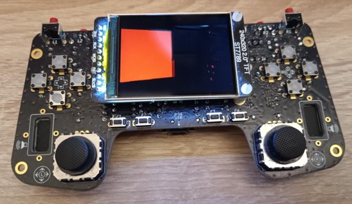
Animations/Videos
In the original code, the entire animation file—often larger than 1 MB—is loaded into RAM. It contains bytecode that is interpreted by the animation rendering engine, allowing for significant data compression compared to storing all frames directly. The animation is first rendered into a temporary 320×200 buffer, which is then scaled up to the target resolution.
Fortunately, the animation file can reside in external flash memory. We only need a 1 KB temporary buffer (allocated on the stack), which is replenished with bytecode as needed.
Additionally, instead of rendering each frame to a separate 320×200 buffer and then scaling it to 320×240, we rewrote the drawing routines. These routines now account for the 1.2× vertical scaling factor and draw directly to the display buffer (320×240). This means that for certain vertical coordinates—specifically, one out of every five lines—each pixel generated by the animation engine results in two pixels being drawn, ensuring proper scaling without the need for an intermediate buffer.
Screen Tilting
Screen tilting occurs when the player looks left or right, or upon death. In the original code, the scene is rendered into a 320×320 pixel buffer (regardless of the actual screen resolution), and the resulting image is then rotated and zoomed before being copied to the screen buffer. Since allocating an additional 100 KB buffer is not feasible, we implemented a trade-off between visual detail and functionality when tilting is required:
- The image is initially rendered into a 160×160 pixel region within the display buffer. This is done only after the previous frame has been sent to the display to avoid visual glitches.
- In the main loop—where stack usage is minimal—we call a function that copies this 160×160 region into a temporary buffer on the stack (25.6 KB).
- The same function then rotates and scales the 160×160 image to fit the 320×200 display area.
This approach means that while normal gameplay maintains high visual detail, the level of detail is reduced during tilting events, such as when the player dies or performs a side-look.
Sound, reverb and music
The sound engine has been modified to optimize RAM usage. In particular, the original implementation contained redundant data and used a linked list structure, which was unnecessary given the limited number of sound channels. Replacing it with a fixed-size array introduced minimal overhead and simplified the design.
The engine supports looped samples and dynamic pitch adjustment. As a result, sound samples can have arbitrary sample rates and are decimated or interpolated on the fly—without filtering.
The original sound engine also featured a basic reverb effect, which has been reimplemented here. Chocolate DN3D, based on xDuke, included an enhanced reverb engine that simulated multiple reflections, surface interactions (e.g., vibration and resonance), and muffling. However, this advanced system requires significantly more RAM and was not included, as the original DN3D did not support such features.
Music playback is handled by a custom MIDI interpreter, which interfaces with a modified AdLib MIDI command executor and voice allocator. This system connects to an adapted version of the OPL2 emulator we originally developed for Doom (which was based on Nuked-OPL3).
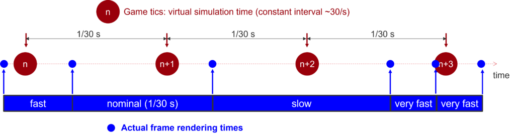
Interpolations
Regardless of system speed, the game logic—handling physics, enemy behavior, and other core routines—is executed 30 times per second. In Doom, this occurs 35 times per second, and these intervals are known as gametics. However, this approach imposes a frame rate cap (famously, Doom is limited to 35 fps). To overcome this limitation and provide smoother visuals, Duke Nukem 3D interpolates the positions of objects (sprites, sectors, walls, etc.) to generate intermediate frames when the system can render faster than 30 fps. This technique is also used in advanced Doom ports to bypass the 35 fps cap.
By using a more precise timer, it’s possible to calculate the fractional progress between gametics. With knowledge of both the previous and current tic positions of an object, the interpolated position can be computed as:
interpolated_pos = previous_tic_pos + (current_tic_pos – previous_tic_pos) * fraction
The interpolator temporarily replaces current_tic_pos with interpolated_pos for rendering. However, doing so would overwrite the actual current_tic_pos needed by the game logic for the next gametic. To avoid this, current_tic_pos must be backed up and restored after rendering the interpolated frame. This would normally require storing three sets of data for each moving object:
- The previous position
- The interpolated (i.e., rendered) position
- The current tic position
To reduce memory usage, we instead store only the interpolated value and the difference between the start and end positions of the current tic.
Tracking coordinate changes for every wall, sector, etc., would still consume significant RAM. To address this, DN3D uses a pool of interpolation slots. When the game logic detects that interpolation is needed for a coordinate or floor/ceiling height (e.g., a sector is rising), it allocates a free slot from the pool. Originally, this was done using 32-bit pointers to the values, which consumed a lot of memory. Instead, since walls and sectors are stored in arrays, we can refer to them by index, along with a flag indicating which field requires interpolation (e.g., x, y, floor height, etc.).
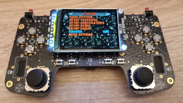
Save Game and options
As in Quake, we fully implemented the save game functionality, with the only exception being that save names are automatically generated. While we could have allowed users to enter custom names via the keypad, this would have been painfully slow. As in DN3D, we also save a screenshot alongside the game state. This is handled as follows: before the menu is displayed, the scene is always rendered. If the user selects a save slot, a flag is set so that in the next cycle—when the scene is rendered—it is also saved to external flash memory, already scaled down to 160×100 pixels.
When loading a saved game, the screenshot is retrieved and directly copied to the appropriate position on screen. Notably, if the same level is being reloaded with the same difficulty setting, the load time is just a few tens of milliseconds.
Options have been implemented as well and they can be saved. You can also remap each key, including the analog thumbsticks.
Oh no, again script, C-var and console!
Literally these three things were the most boring parts to implement in our Quake port. Luckily:
- The script is compiled by the game. We have just extracted the code that compiles the GAME, USER and DEFS.CON files. The resulting arrays are printed in C-friendly format to the console and then copy & pasted in con_file.h. Notably, the compiled game script uses pointers which are also position dependent. Instead, we use array indexes, as the compiled script is below 65536 entries.
- C-vars really needed minor changes to be MCU friendly.
- The console uses malloc (yes, a sixth allocator!), to allocate buffers. We have optimized the way text is stored (using dynamically-sized structure members – as opposed to static array size). Still the amount of RAM left for heap is very small (few hundred bytes) so very few lines can be printed. That’s not a huge issue, as unlike Quake, the console is not visible by default, and only plays a minor role.
Caching to flash
In previous ports, we extensively used caching of both common and level-specific constant data to flash memory to reduce RAM requirements and also to increase speed (compared to leaving to external flash). Common data remains unchanged after the game’s first run and includes elements such as palette information or the list of files and their locations within DUKE3D.GRP. Level-specific data depends on the selected level and skill, and includes information such as walls, sectors, sprites, and hittype data.
Also, unlike in our Quake port —and more similarly to our Doom ports— in DN3D we also cache a significant amount of graphical data to flash memory. Specifically, we focus on caching floor and ceiling textures and sprites because, during their rendering, their data is not accessed sequentially as it is for walls and vertical sprites instead (see Appendix A for more details). In fact, while reading sequential data is reasonably fast even from external flash (up to 17 MB/s), random reads are very slow (see Appendix B for more details).
If a texture resides in external flash, random read access can take some microseconds per pixel, resulting in a maximum read speed of only a few hundred thousand pixels per second. In some cases, these textures can account for 50% or more of the rendered pixels—roughly 32,000 pixels per frame. Accessing that many pixels could take up to 60 ms or more, severely impacting performance. Reading from internal flash is more than 10 times faster.
When deciding which texture shall be cached to internal flash, we sort them by size, and we cache the larger ones first. Smaller textures, on the other hand, can remain in external flash and they are loaded into a temporary RAM buffer when needed. Loading a small texture (4–8 KB) is very fast—less than 0.5 ms for 8 KB—and once in RAM, it can be accessed with zero wait states, even faster than internal flash. We prioritize large textures for internal caching because smaller textures can be loaded more quickly and they require a smaller RAM buffer.
Atomic Edition Support
Although initially out of scope, we eventually decided to support the Atomic Edition to avoid comments like, “Oh, you’re only supporting the base Duke Nukem 3D without the Plutonium Pack/Atomic Edition? How lame!” The Atomic Edition introduced significant complexity by adding more tiles—many of which are much larger, especially floor and ceiling textures. To accommodate this, additional effort was made to reduce flash usage by over 160 KB.
A substantial portion of this reduction came from enabling link-time optimization and disabling speed-focused optimizations in opl2.c and engine.c. Further savings were achieved by optimizing the size of certain structures cached to flash.
Other optimizations, stack, and memory reusage
As we mentioned before, some arrays were declared as global, whereas they could have been in stack. Stack usage is not constant throughout the code (e.g. game or 3D renderer), so when we found that moving a previously global array to the stack did not increase peak stack usage, we went ahead and did it.
On the other hand, the frame buffer and some other big arrays that contain the state of the objects (like hittypes, ramwalls, etc.) represent a good temporary buffer, which can be used when 3D rendering is not required. For instance, we use the frame buffer during level loading. Also, we are reusing another array to hold the partial animation bytecode.
Yes, this is horrible bad coding, which could have been avoided, for instance by using dynamic memory allocation, however we felt that it was not worth the effort.
Speed optimization
Many of the drawing routines were optimized for x86 architecture. These were translated into C code, creating extremely hard-to-read code. We have optimized and cleaned up some of them, still a lot of work has to be done.
We also have resumed some tricks we used in Doom:
- Asynchronous column loading and rendering. When drawing sprites and walls stored in the external memory, we load via DMA the next column to be rendered, while we are rendering the current one.
- For close textures, if the same column is being used twice, the loading is skipped.
- We avoid loading the entire column: we just load as many pixels as we need (plus 4-bytes alignment).
- There are a lot of palette look-up tables (LUT), which would not fit in RAM, so they stay in flash. However, as flash is slower than RAM, instead of accessing the LUT directly from flash, we copy it to RAM. When drawing a column, we check if the same LUT is being accessed or not, saving the copy operation.
- Caching to flash. As we wrote before, caching to flash not only helps reducing RAM usage, but also can bring significant speed improvement with respect to directly accessing data from external flash. In particular, the previously mentioned floor/ceiling caching to flash is of fundamental importance to achieve good frame rate values.
- Caching to RAM. If we must draw something which was already loaded to RAM, we skip loading it again from external flash to RAM.
- Blockmap. We want to address this in its separate section because it brought a significant improvement in some conditions.
The blockmap. But not exactly as Doom’s blockmap.
We borrowed the blockmap concept from Doom to accelerate the updatesector() function in DN3D. While the underlying idea is similar, its role differs between the two games: in Doom, the blockmap is used exclusively for collision detection, whereas in DN3D, it helps determine the sector in which a sprite is located—essential for rendering. Additionally, Doom’s blockmap contains linedefs, while DN3D’s version contains sectors.
In DN3D, whenever a sprite changes position, its sector must be updated. Typically, sprites move slowly, so they either remain in the same sector or transition to one directly connected via a passage. The original algorithm first checks whether the sprite is still in its previous sector. If not, it scans all neighboring sectors. If the sprite is still not found, the algorithm proceeds to scan all sectors.
Determining whether a point lies within a sector involves checking how many walls intersect a horizontal line at the same y-coordinate as the point—using the ray casting algorithm (http://en.wikipedia.org/wiki/Point_in_polygon#Ray_casting_algorithm). This requires scanning all walls in a sector. If the number of intersections is odd, the point is inside; if even, it’s outside.
Although the original algorithm is highly optimized, the worst-case scenario involves scanning all sectors and, in turn, all walls—which can number in the thousands. On average, about half the sectors are scanned, but there are edge cases where sprites are generated outside the map, requiring a full scan. This happens, for example, with exploding walls: debris is randomly generated near the wall with random directions. If a sprite is spawned inside the wall or directed toward it, it may end up outside the map.
One such case occurs in E1L1, inside the cinema.
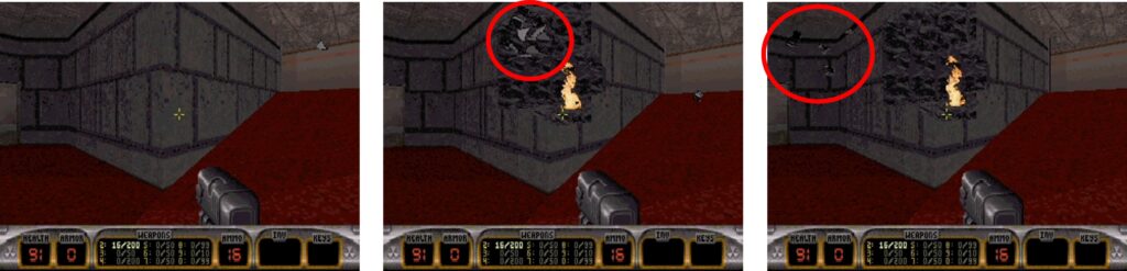
Despite the map being relatively small (around 2,000 walls), we experienced severe framerate drops—down to 10 fps in some cases—which is clearly unacceptable. We found that this issue also occurs on older, slower PCs and in other DN3D ports, as we’ll discuss later.
In our case, we measured that the updatesector() function consumed approximately 250,000 clock cycles per sprite during these edge cases. At 136 MHz, this translates to less than 2 ms per sprite. However, when many sprites are generated inside walls, the cumulative cost becomes significant. Dropping from over 30 fps to 10 fps implies a slowdown of more than 66 ms per frame, which cannot be explained by a mere 2 ms per sprite—indicating a much deeper performance bottleneck.
However, this can trigger a form of positive feedback. To understand why, let’s look at a simplified version of the game loop*:
LOOP:
  Get ticks Elapsed Since Last time
  For Each Elapsed Tick:
    domovethings()
  End For
  Render Frame
Go to LOOP
* Note: In Chocolate DN3D, the structure is slightly different. The faketimerhandler() function is called in many parts of the code, including during rendering. If the time elapsed since the last faketimerhandler() call exceeds 4 ticks (with 120 ticks per second, i.e. one per gametic, as there are 30 gametics per second), input from the keyboard, joystick, and mouse is queued. This simulates a periodic interrupt for input collection. The input queue is then processed in moveloop(), which calls domovethings(). In our implementation, faketimerhandler() is called only four times in the LOOP.
If domovethings()—which includes calls to updatesector()—takes too long to execute, the number of ticks elapsed increases. On the next iteration, domovethings() is executed multiple times to catch up, further increasing the elapsed ticks, and so on. This creates a feedback loop where performance continues to degrade.
Notably, the engine does not remove sprites that are outside the map, so subsequent calls to domovethings() remain slow until the sprite is either removed or re-enters the map. As a result, this positive feedback loop can persist for many frames, significantly impacting performance.
To address this issue, we adopted two strategies:
- Removing sprites when debris is outside the map
This simple solution effectively breaks the positive feedback loop. However, it was ultimately disabled for the following reasons:
a) Some sprites, even if initially generated inside walls, may move outside after a few frames. Prematurely deleting them would reduce the visual impact of debris, resulting in a less satisfying effect.
b) This fix only applies to earthquake scenarios and does not address all cases where updatesector() is used.
c) Despite the fix, frame rates could still drop below 20 FPS—in some cases reaching as low as 19 FPS. - Implementing a blockmap
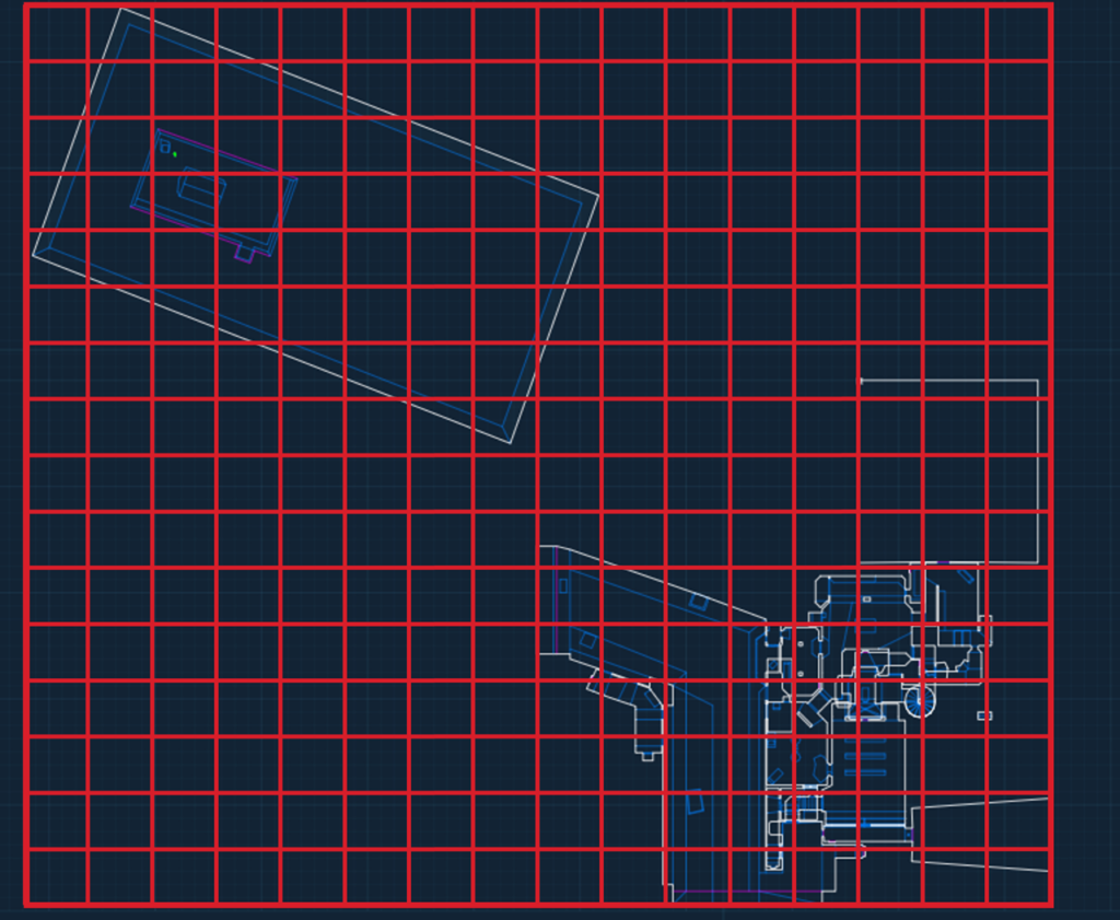
The blockmap divides the entire map into a regular grid of blocks. The number of rows and columns is fixed—we currently use 16 rows and 16 columns—and the grid is sized just large enough to fit the entire map, optimizing RAM usage. We found that a 16×16 matrix offers a good trade-off between performance and flash memory usage. Smaller maps benefit from finer resolution, as they still fit within the 16×16 blockmap, resulting in smaller block sizes.
For each block, we check which sectors intersect or touch it. If no sectors are present, the block points to NULL. Otherwise, it points to a list of int16_t values, each representing a sector that intersects the block. The list is terminated with -1 to indicate the end.
This approach enables us to quickly identify which sectors might contain a given (x, y) coordinate, significantly narrowing the search to a small subset—typically just a fraction of the total sectors.
As a result, we modified the updatesector() function. Unfortunately, DN3D allows sectors to exist within other sectors, meaning the order in which sectors are checked does matter. Specifically, we must ensure that sectors with higher indices are checked first.
The updated algorithm first checks the previous sector, followed by its directly connected neighbors. If none of these contain the sprite, we use the blockmap to retrieve a list of candidate sectors to search.
However, as previously mentioned, walls can move. To handle this, we modified the dragpoint() function and introduced an array of bitfields. Whenever a wall is modified, we mark its corresponding sector(s) as modified.
After determining whether a sprite is inside a sector (or not), we then check all modified sectors whose index is strictly higher than the one previously found (or -1 if none was found). If a modified sector in that range contains the sprite, we update the sector index accordingly. Otherwise, we fall back to the index obtained from the blockmap list (which may be -1 if no match is found).
The performance improvement was dramatic: the framerate remains in the 30 fps range even during earthquakes that cause walls to explode in E1L1. The blockmap is fully cached to flash, and approximately 120 bytes are used to track modified sectors.

Multiplayer over 15.4
Multiplayer was supported in DN3D, but only via command-line. To start a multiplayer match, users had to launch DN3D with specific CLI parameters, which would initialize the transport layer using UDP. The multiplayer code appears to have been optimized for low-speed connections and includes a particularly difficult-to-read error-handling implementation.
Fortunately, the transport layer is fairly well separated from the game logic. Since our platform includes a radio, we were able to implement multiplayer over radio. The choice of protocol was constrained by several factors:
- We aimed to maintain a very small footprint, which ruled out BLE and other full protocol stacks such as Thread or Zigbee. Instead, we used the RAIL library—Silicon Labs’ low-level radio abstraction interface.
- On System-on-Chip versions (e.g., EFR32MG24 MCUs), RAIL allows full customization of radio parameters. However, on modules (MGM240P) and System-on-Modules (MGM240S), RAIL only supports either full protocol stacks (like BLE) or, at the lowest level, the IEEE 802.15.4 PHY and MAC layer specifications.
Therefore, we opted for the IEEE 802.15.4 protocol and implemented a lightweight communication layer on top of it. The operational principles are as follows:
- All devices reside within the same PAN (Personal Area Network), with the default PAN ID set to the hexadecimal representation of “DN”.
- Each device randomly selects a short address, which also serves as its client ID. The short address must not be 0 or 0xFFFF.
- Devices only send broadcast packets.
- All packets are “signed” in a basic way using a custom CRC32. This CRC is not used for error detection (as the radio already appends a CRC16), but rather to verify that the packet originated from a DN3D peer, and not from a random Zigbee or Thread device operating on the same channel and PAN ID.
- Two communication modes are supported: asynchronous and synchronous, described below.
Asynchronous Communication
This mode is used when devices have not yet discovered each other. Each device can send packets using the CSMA-CA (Carrier Sense Multiple Access with Collision Avoidance) mechanism. Devices sense radio activity and, if detected, wait a random backoff period before retrying. This method is used during the greeting phase, allowing peers to detect each other’s presence. Aside from the CRC32 signature, there is no error recovery or detection, as these packets are sent frequently to ensure other peers can receive them at least once.
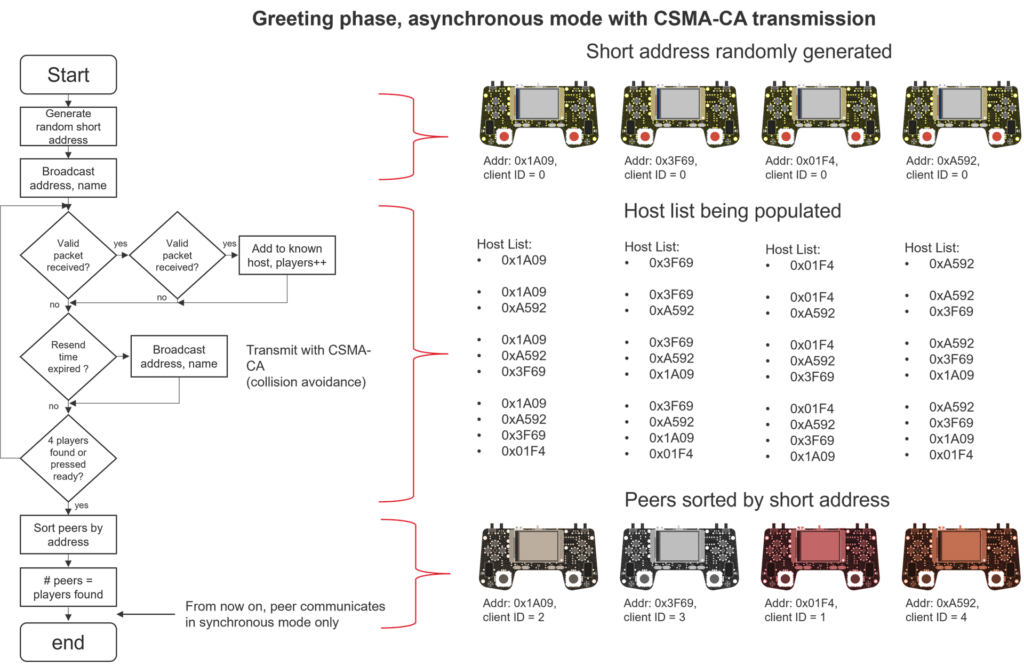
Synchronous Communication
This mode resembles old token-ring network protocols. Once all devices are discovered (e.g., four devices are detected or the player presses “Ready”), they are sorted by their short address. The device with the lowest address becomes Client 1 and acts as the master.
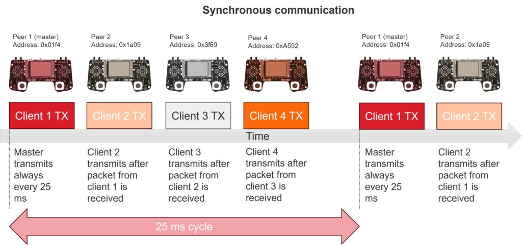
The master begins broadcasting a radio packet every 25 ms, without using CSMA-CA. Upon receiving the packet, Client 2 broadcasts its own. Similarly, Client 3 transmits its data after receiving Client 2’s packet, followed by Client 4 after receiving Client 3’s. In a traditional token-ring setup, Client 1 would transmit again after receiving Client 4’s response. However, we chose not to follow this pattern to avoid excessive radio traffic with no practical benefit. High traffic could degrade performance, as each received packet triggers an interrupt service routine (ISR) and requires processing.
Instead, Client 1 resumes transmission when the next 25 ms timer interval expires.
The following picture summarizes the process:
Due to packet loss and varying frame rates, the game may enqueue multiple subpackets in the transmit queue. A subpacket refers to a packet generated by the game logic using the sendPacket() API. To prevent overflow, the protocol attempts to pack as many subpackets as possible into a single radio packet. If a subpacket does not fit, it will be sent in a future packet—even if there is remaining space for additional bytes.
Furthermore, subpackets are sent in order. This means that if a larger subpacket cannot fit, smaller subsequent subpackets are also excluded, even when some of them could fit within the remaining space. These subpackets will be sent later in a new radio packet.
The packet structure is shown below.
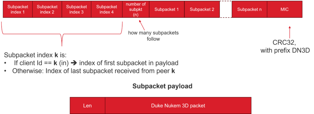
Subpackets in the transmit queue are freed once a peer detects that all other peers have received the subpacket. This is determined by inspecting the header of each incoming packet’s payload. The header contains four 4-byte subpacket indexes and a field indicating the number of subpackets included in the payload.
These four indexes serve different purposes: the index at the position corresponding to the client’s own ID (e.g., the first 4 bytes for the master, the second for Client 2, etc.) indicates the subpacket index of the first subpacket in the payload. The remaining indexes represent the number of subpackets that have been received or queued from each respective peer. This allows each peer to determine which subpackets in their transmit queue can be safely discarded.
In this way, each peer communicates both what it is transmitting and how many packets it has received from others. Conversely, receiving peers can infer which of their sent subpackets have been successfully received and processed.
When a radio packet is received, it is split into subpackets. Some of these may already exist in the receive queue or may have already been processed—these are discarded. Any new subpackets are enqueued into the receive queue until it reaches capacity. Subpackets that do not fit are simply discarded. This is not a problem, as the receiver will notify this with the subpacket index to indicate that fewer subpackets were received or processed. This feedback prompts the sender to retransmit the missing subpackets during its next transmission turn.
This protocol has several issues:
- It is not focused on security at all. That said, this project is merely a proof of concept for porting a game.
- It is quite inefficient:
- We are sending 17 bytes just to handle missing packets.
- If Client 2 misses a radio packet from Radio 1, it won’t send its own packets. As a result, Clients 3 and 4 won’t transmit either—even if they successfully received Client 1’s radio packet.
- We transmit without checking whether the PAN ID and short addresses are already in use by other non-DN3D devices.
- In synchronous mode, we transmit blindly, without verifying whether other non-DN3D devices are using the same channel.
- If a client reboots or hangs, the entire match is lost. However, if a client temporarily goes out of range and then returns, the match can continue once the device is back within range.
Despite these drawbacks, the protocol is very lightweight and quite robust against packet loss.
Script for DUKE3D.GRP conversion
DN3D used Type-1 MIDI songs, which include multiple tracks. This increases both complexity and memory usage, even though MIDI Type 0 could have been used as well without loss of audio features. Additionally, DN3D used VOC sound files, which are more complex than WAV. However, the advanced features of VOC that might justify their use are not utilized by the audio engine, rendering them unnecessary. For instance, although VOC supports loops starting in the middle of a sample, we have verified that DN3D does not use this capability—a sample is either fully looping or not.
Since supporting Type-1 MIDI songs and VOC files would require additional code and RAM, we developed a Python script that processes the DUKE3D.GRP file and converts all MIDI files to Type 0 and all VOC files to 8-bit WAV format. The sample frequency remains unchanged, as the sound engine supports varying sample rates. This decision is based on the fact that DN3D applies pitch variation to the same sound effect to introduce randomness.
We provide the instructions about how to use the script in the “Building” section.
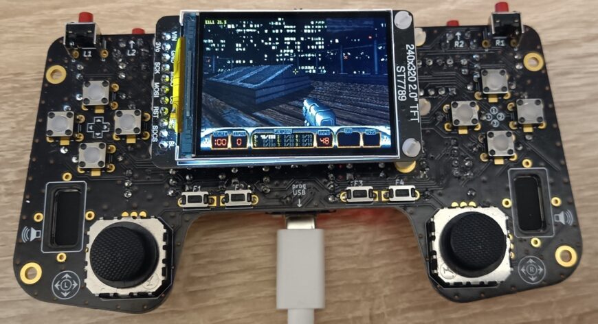
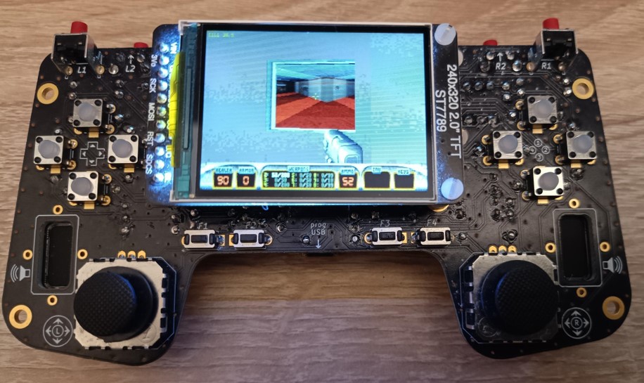
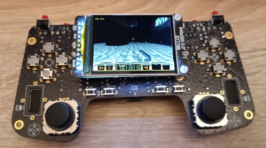
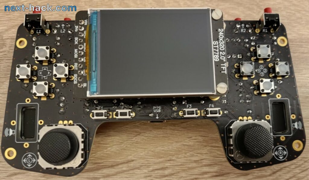
Hardware
This time, we did not use any new hardware. The port supports both consoles we developed previously: the Gamepad, based on the Arduino Nano Matter, and the earlier version using the SparkFun Thing Plus Matter. The full DN3D GRP 1.3D file fits within the 32 MB flash, leaving a few megabytes available for settings and save games. The Atomic Edition, however, requires 45 MB, so two 32 MB flash ICs are needed.
Note that although the older console with the SparkFun board can technically run DN3D, it lacks sufficient keys for proper gameplay. We support it only because of its built-in J-LINK debugger and its compatibility with Ozone and Simplicity Studio.
Building
To build the game, you must follow the exact same steps we used for Doom and Quake, so we encourage you to read the previous articles for guidance.
We just summarize here the steps:
- Install Arduino.
- In Arduino install the support for Silicon Labs boards (Arduino Nano Matter). This will install the required tools to actually flash the binaries to the Arduino Nano Matter boards.
- Install Simplicity Studio 5.
- Install SiSDK 2025.6.2 in Simplicity Studio.
- Download/clone the github repository https://github.com/next-hack/MGM240_DukeNukem3D.
- Import the MGM240DN3D project into Simplicity Studio 5.
- Build the project. It should compile without warnings.
- Open the binary folder “The Gamepad (Arduino Nano Matter)” containing the generate binaries.
- From there, launch “CopyToArduinoMatterBoard.bat” file, which will use tools installed in points 1-2 to flash the binaries.
Once you’ve built and flashed the binaries, you’ll need to store the data file in external flash memory. This file is called DUKE3D.GRP. You can use one of the following versions:
- The shareware GRP file available from the 3D Realms website.
- The full GRP file from the original game (version 1.3d).
- The full GRP file from the Atomic Edition.
Nowadays, legally acquiring the 1.3d GRP file is difficult—you must either already own it or purchase an old-stock DOS Duke Nukem 3D CD, which can be expensive, especially with shipping costs. The Atomic Edition, however, can be legally purchased digitally from Zoom Platform for just a few dollars. Steam also offers the 20th Anniversary World Tour at a reasonable price, but based on our understanding, the bundled GRP file is not compatible.
Unfortunately, the Atomic Edition GRP file is larger than 40 MB, so you’ll need two 32 MB flash ICs. If you only have two 16 MB ICs, you can downgrade to the 1.3d version by using the -downgrade option in the script.
How to Use the Script
- Copy mcugrpcvt.py and DUKE3D.GRP into a directory.
- Open a command line window.
- Install the mido library by entering: “pip install mido”
- Navigate to the directory where DUKE3D.GRP and mcugrpcvt.py are located by issuing “cd <path_to_mcugrpcv.py>”, where <path_to_mcugrpcv.py> is the full path where you placed the aforementioned files.
- Enter: “python mcugrpcvt.py DUKE3D.GRP”
- You can optionally specify an output filename, e.g., “python mcugrpcvt.py DUKE3D.GRP MY_DUKE3D_CONV.GRP”. If no name is provided, the default output will be DUKE3D_CONV.GRP in the same directory.
- You can optionally specify –downgrade, if you need to convert the Atomic GRP to regular GRP, to fit 32 MB flash (2×16).
- Copy the resulting file to a microSD card (renamed to DUKE3D.GRP).
- Insert the SD Card on the right side of the display.
- Turn on the device and follow the on-screen instructions to flash the GRP file to external flash memory.
Important: After flashing, remember to remove the SD card to prevent graphical glitches. These can occur because the SD card shares the same SPI bus as the display, and the clock frequency is about 68 MHz.
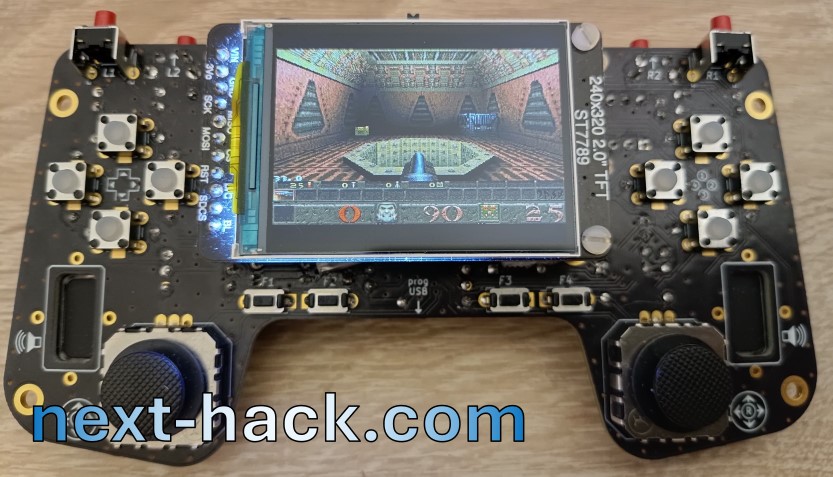
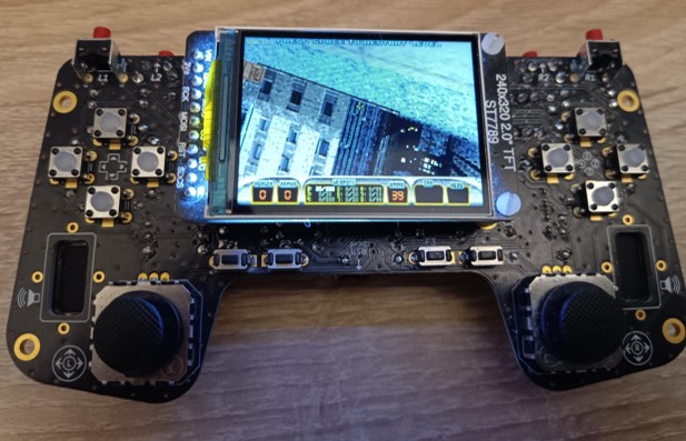
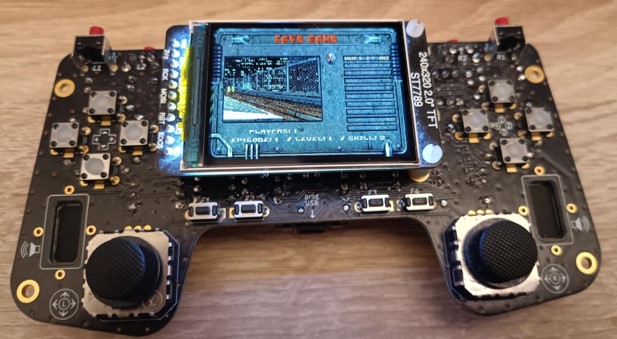
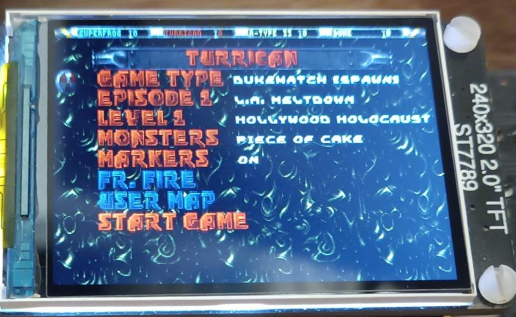
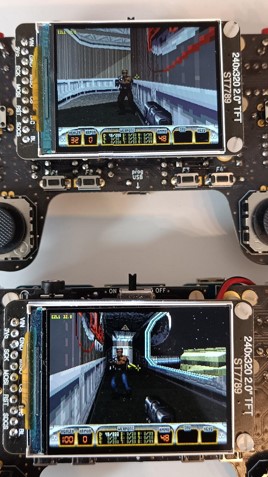
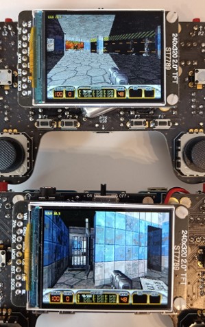
Some More Pics
Although we have put several pics in the article, we want to show more, highlighting that all the features were implemented.
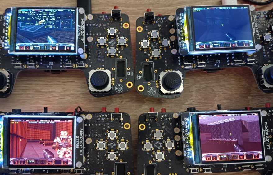
A video
You can watch the video here where we show a 4-player match on E3L1.
Performance and comparison
Unfortunately, unlike Doom and Quake—both of which have well-documented benchmark results available online—finding solid performance references for Duke Nukem 3D is quite difficult. While there are numerous websites, forums, and social media posts discussing performance, the information is scattered, often contradictory, and highly subjective (e.g., “it’s fast!”, “very slow”). Moreover, there is no standardized testing methodology or aggregated benchmark table. That said, it is generally accepted that DN3D ran slower than Doom but significantly faster than Quake.
Comparing our port to the Game Boy Advance version of Duke Nukem 3D is not an apples-to-apples comparison. Our version is a full port of the complete game (including the Atomic Edition), whereas the GBA version uses entirely different maps optimized for low RAM usage. Based on gameplay footage available on YouTube, it appears that many features were stripped down to fit within the GBA’s limited memory (384 kB).
We did find at least an example of DN3D being ported to ESP32 chips (such as https://github.com/jkirsons/Duke3D), which uses 4 MB of PSRAM. After analyzing the code, we found that aside from hardware configuration differences, the main optimization was placing certain data and functions in faster internal SRAM instead of flash (which is QSPI and significantly slower). Other than that, the code is essentially identical to the Chocolate DN3D sources. That port runs at a resolution of 320×200 pixels, apparently without music, and multiplayer seems to be disabled (although the code exists, Chocolate DN3D enables multiplayer only via CLI or config file).
There are two videos showcasing that ESP32 port. In the first (https://www.youtube.com/watch?v=S-DgYw0V4NQ), the frame rate is displayed and is often in the single digits. In the second (https://www.youtube.com/watch?v=2KxK3Vb0524), the author doubles the PSRAM frequency to 80 MHz, resulting in visibly smoother gameplay—though no FPS counter is shown. Since only the PSRAM frequency was increased, we estimate the frame rate roughly doubled. By analyzing the second video frame-by-frame, we measured around 15–20 FPS, which is about half the speed of our port.
That ESP32 setup includes 520 kB of SRAM, a CPU running at 160 MHz, and 4 MB of external PSRAM. While external PSRAM is slower than our internal flash (used for code and texture caching), it benefits from QSPI’s sequential read speeds of up to 40 MB/s—much faster than the 17 MB/s we achieve with our interleaved SPI flash memories. Additionally, the ESP32 uses caching for both QSPI and PSRAM, and many functions and data are placed in RAM. We estimate that 256 kB is sufficient to hold all speed-critical functions, leaving another 256 kB for data.
In our case, with overclocking enabled, the frame rate consistently stays above 30 FPS, occasionally dipping to the 20s and often reaching into the 40s. In some cases, it even exceeds 50 FPS.
Compared to our Quake port, this is significantly faster—despite DN3D using a larger 3D viewport (320×200 pixels vs. Quake’s 320×152 pixels), and including multiplayer and OPL2 music emulation. This aligns with historical performance: DN3D was simpler and faster than Quake back in 1996.
Without overclocking, performance is approximately 1.7x slower, averaging above 18 FPS and peaking at 27–30 FPS. Even then, it outperforms the ESP32 port, which runs at twice the frequency, with lower resolution, no music, and no multiplayer.
Lack of double buffer
At this point, it is worth evaluating how much the lack of double buffering affects performance.
In fact, if we had more RAM—say, an additional 64 kB—we could have implemented double buffering. The question is: how much would we have gained from it?
To estimate the potential improvement, we disabled the waitForDisplayDMA() function by simply inserting a return statement. This simulates the behavior we would expect with two frame buffers: one would always be free, eliminating the need to wait.
Note: inserting this return causes severe visual glitches.
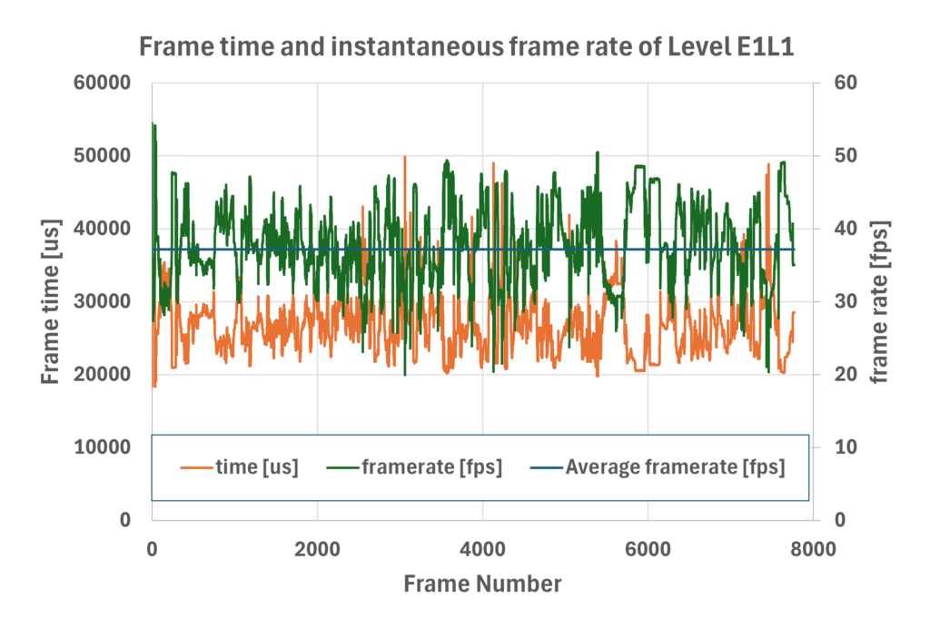
We used the E1L1 level as a benchmark and waited until the exploding ship crashes, allowing the frame rate to stabilize.
- In regular gameplay (without the return), the frame rate is a steady 31.5 fps.
- With the return inserted, the frame rate increases to between 37 and 43 fps.
This implies that the CPU is busy for 23 to 27 ms per frame. The display update time (assuming 200 lines and no status bar) is about 15 ms, meaning the bottleneck is not the DMA, but the CPU—handling rendering, game logic, audio, and music—which takes an additional 8 to 12 ms.
Still, the performance gain from double buffering would be noticeable.
Conclusions
It seems that “640 kB ought to be enough for everyone” still holds some truth—this is the third game we’ve successfully ported to around 256 kB of RAM (Quake used 276 kB, as the radio component was not included).
We’ve implemented everything except demo recording and playback. That doesn’t mean we won’t bring it back in the future :).
The port runs fast, and all major features are implemented. Multiplayer is supported, although limited to 4 players. Options can be fully saved, and savegames are supported as well. There’s also a console where you can enter cheats.
Despite the good performance, we haven’t spent much time on optimization yet. We believe there’s still room for improvement, and we could likely gain a few more FPS with further tuning.
Finally, we hope you find this port insightful, and we’re excited to see what you’ll be able to do with it!
Appendices
We decided to put here some more technical details that might not be essential for the whole article.
Appendix A: Vertical walls and horizontal floors/ceiling
In this appendix, we explain the significant differences between rendering vertical walls and horizontal textures such as floors/ceilings. By “horizontal,” we refer specifically to floors and ceilings that are perpendicular to the player’s camera. Sloped floors, on the other hand, use a different rendering technique that still requires random reads.
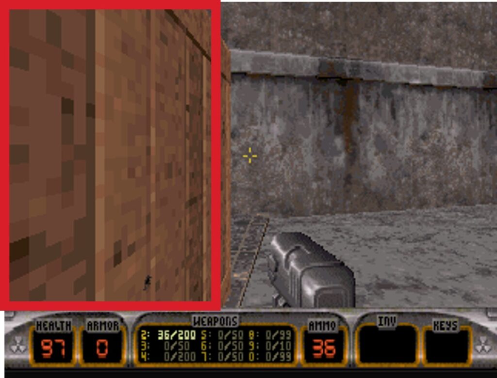
Let’s suppose we want to render the scene shown in the top-left part of the figure below. Specifically, we aim to render the slice of wall highlighted by the yellow rectangle. The top-right section of the figure shows a zoomed-in view of this yellow area, including a grid to distinguish individual pixels.
Since the wall is vertical, all pixels in each column are equidistant from the screen plane. As a result, each column is essentially a scaled version of the corresponding column in the original texture. In the bottom-right part of the figure, we highlight in red and green the columns read from the texture. Green pixels are rendered on screen, while red pixels are read but not displayed due to column shrinking.
Note that although the bottom-right part of the figure shows the texture as it appears on screen, it is actually stored transposed in the game data—that is, organized by column. This allows for sequential reads, which are faster and can be performed via DMA.
If the texture resides in internal flash memory, we simply read the required pixels directly when needed. However, if the texture is stored in external flash, we first use DMA to copy the relevant column—or more precisely, the range from the first to the last used pixel—into a small temporary buffer in RAM, and then we use such RAM buffer for random reads during rendering.

Top left: example 3D scene.
Top right: zoomed view of the yellow rectangle region, showing some rendered columns.
Bottom right: The wall texture, with rendered columns highlighted in red. For each column, the actually drawn pixels are marked in green. Note that although the texture is shown to resemble its on-screen appearance, it is stored column-wise—i.e., pixels of the same column are stored sequentially. This allows us to load a single column into a RAM buffer, which is then used to fetch data for rendering.
Bottom left: zoomed view of the floor texture, with the actually rendered pixels for the highlighted blue region (1-pixel wide) shown in blue. Notice how the texture is traversed at an angle; therefore, the entire texture must either reside in internal flash or be loaded into a large temporary RAM buffer.
Horizontal textures—such as floors and ceilings—are rendered very differently from vertical walls. They are drawn row by row rather than column by column. This is because all pixels in a given screen row that belong to a horizontal texture share the same distance from the screen plane. Rendering them by column would require a perspective correction (i.e., a division) for each pixel, which would significantly slow down the rendering process.
Unlike walls, floor and ceiling textures are almost always accessed non-sequentially. This is illustrated in the bottom-left part of the figure, where all accessed pixels are highlighted in blue. Loading these pixels from external flash would be time-consuming. Therefore, whenever possible, floor and ceiling textures are stored in internal flash.
Since not all floor/ceiling textures fit in internal flash, the smaller ones (typically 4–8 kB) are kept in external flash and loaded into RAM when needed. Loading a continuous 8 kB block takes less than 500 microseconds. If we had to read 320 pixels non-sequentially from external flash—for example, to render a single horizontal row with a floor texture—it would take roughly the same amount of time. However, in the former case, the data loaded into RAM can be reused to render multiple screen rows, effectively amortizing the 500-microsecond load time across several rows. In contrast, pixel-by-pixel reads would consistently take about 500 microseconds per rendered row.
Appendix B: Flash read speed
The MGM240S is based on the EFR32MG24 SoC, which includes 1.5 MB of internal flash memory. Unlike the ESP32 or RP2xxx, this flash is parallel—meaning it has separate address and data buses, along with dedicated control signals.
To read a single byte, the system simply provides the address, and after a few clock cycles, the data becomes available. The CPU (Cortex-M33) performs this read using the LDRB instruction, which takes 2 + nW cycles, where nW is the number of flash wait states (2 in this case). At a clock speed of 136.5 MHz, this results in a latency of around 30 ns, allowing data to be loaded into a register at roughly 34 MB/s.
If instead a full 4-byte word is read using the LDR instruction, the speed increases to 136.5 MB/s (note: these values assume overclocking). Using the LDM instruction, more registers can be filled, amortizing the initial 2 cycles, improving throughput.
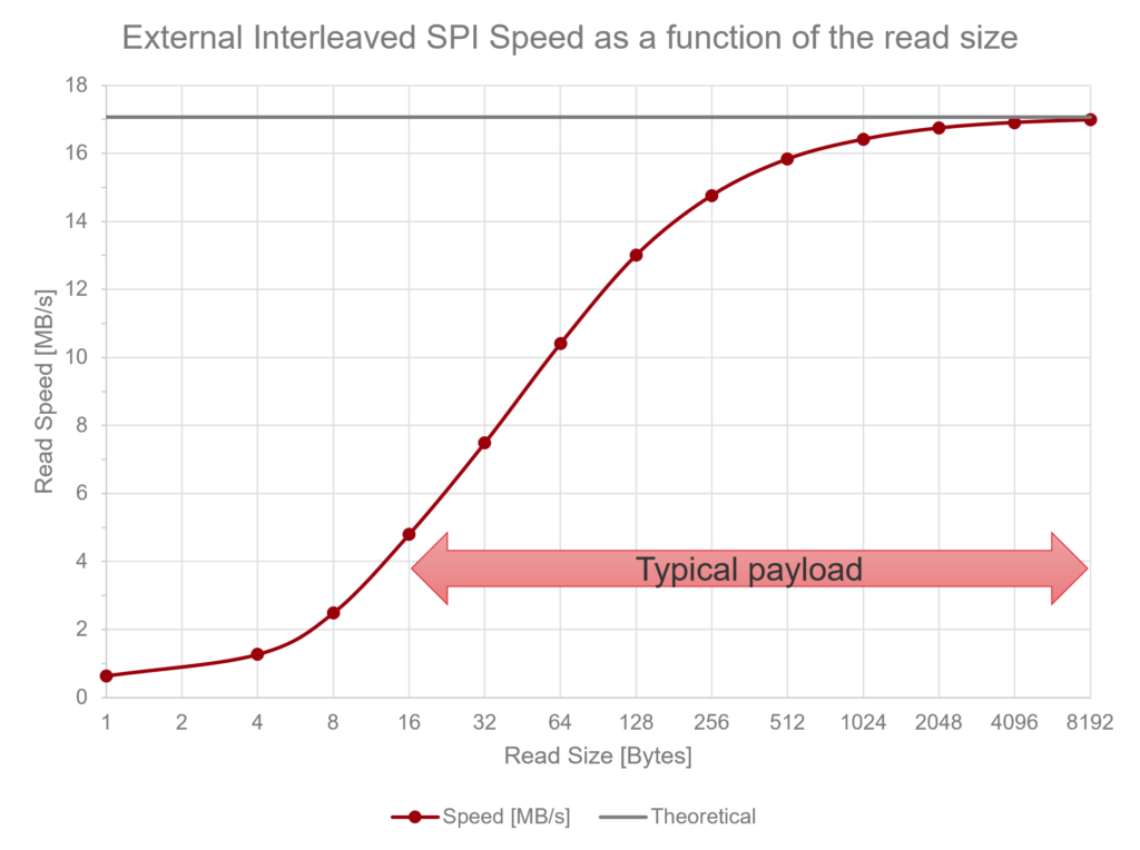
In contrast, reading from external flash is significantly slower—both in terms of latency and peak bandwidth. The peak bandwidth is limited by the SPI clock speed. The system uses two SPI flash ICs, with data interleaved between them (i.e., even 16-bit words are stored in the first IC, odd ones in the second), which improves throughput. Any data block of 4 bytes or more is read simultaneously from both ICs. With an SPI clock of 136.5 MHz / 2, the combined read speed is about 17 MB/s (8.5 MB/s per IC), using DMA. This is already half the speed of random byte reads from internal flash.
However, performance degrades further for small reads due to latency. Initiating a read requires several setup steps, including configuring the DMA and E-USART. Additionally, the system must send a 32-bit address, a read command, and a dummy byte—resulting in a 56-bit SPI transaction for an 8-bit read, which takes about 800 ns. On top of that, the E-USART must be disabled and re-enabled to flush residual data from the read FIFO—a process that takes several tens clock cycles on the MGM240S.
Altogether, this results in a latency of approximately 1.6 µs, corresponding to a read speed of only 600 kB/s—more than 50 times slower than random reads from internal flash.
Below, we show the performance achievable with external flash, highlighting typical payload sizes, which range from 16 bytes (e.g., a small texture column) to 8 kB (e.g., a large floor/ceiling texture loaded from external flash).