
Introduction
(tl;dr. source code and KiCAD project at the end of this page!)
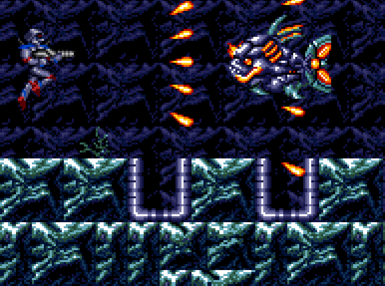
Although we were born in the 8 bit era, our first computer was an Amiga 500. It was a glorious 16-bit machine, and it featured stunning graphics and sound, making it well suited for gaming.
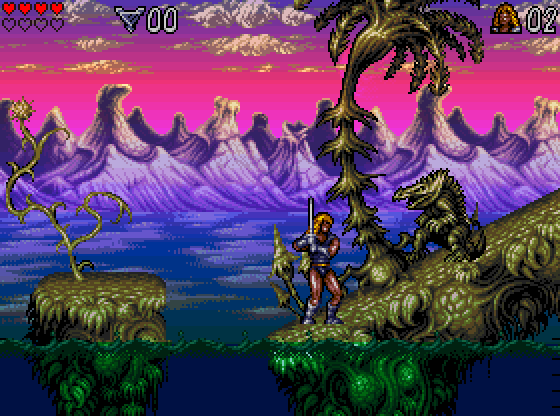
On this computer, a very popular genre of games was the platform. Many of them were very colorful, featuring a very fluid parallax scrolling. This was achieved by talented programmers that ingeniously used the Amiga’s coprocessors to increase the number of on-screen colors. Take a look for instance at LionHeart!
Electronics has changed a lot since the 90s, and now there are plenty of small microcontrollers that allow you to create very spectacular things.
We always loved platform games, and now with few bucks one can buy a Raspberry Zero, install Linux, and program a colorful platformer “quite easily”.
That’s not a job for us, it’s like using a nuke to kill a mosquito!
We want to use microcontrollers, with limited memory, not powerful system on a chip with built-in GPU! In other words: we want some challenge!
Speaking about video capabilities, some people managed to squeeze every drop out of an AVR microcontroller with some projects (like the Uzebox project or Craft by lft). However, to achieve this, AVR microcontrollers force you to write in assembly, and even if there are some examples of very nice games, you’ll face some heavy constraints, that won’t allow to get a 16-bit style game.
Instead, we would like to use some more balanced microcontroller/board, that allowed us to code entirely in C.
Not as powerful as an Arduino Due but not as limited as an Arduino Uno. Interestingly enough, “Due” means 2, and “Uno” means 1. And just like Microsoft taught us how to count (1, 2, 3, 95, 98, ME, 2000, XP, Vista, 7, 8, 10), Arduino cannot be any different! We will use Arduino Zero as intermediate between 1 and 2!
Yes, 1 < 0 < 2, according to Arduino 🙂
In particular, what we are interested in, is not the board itself. Instead, we are considering its processor series. The Arduino Zero mounts an ATSAMD21 series microcontroller, with a 48MHz Cortex M0+, 256kB of flash, and 32kB of RAM.
While a 48MHz Cortex M0+ could largely outperform an old 7 MHz MC68000, the Amiga 500 had 512kB of RAM, hardware sprites, built in dual playfield, the Blitter (a DMA based block image transfer engine, with built in pixel exact collision detection system and transparency) and the Copper (a raster based coprocessor, which allowed to perform register operations based on the raster position, to create a lot of very nice effects).
In the SAMD21 all this hardware is missing (except a rather simple DMA, at least with respect to Amiga’s Blitter), therefore a lot of drawing stuff will be performed in software.
We would like to achieve these features:
- 160 x 128 pixel using an SPI 1.8” display.
- 16 bits per pixel graphics;
- As many fps as possible. At least 25 fps with a 12 MHz SPI clock, or 40 fps at 24 MHz;
- dual playfield with parallax scrolling;
- all in C. No asm code;
- pixel exact collision detection;
- on screen overlay.
These sounds like rather hard to achieve goals.
And they are, especially if asm code is ruled out!
For instance a 160×128 pixel screen takes 40kB for frame buffer at 16 bit, but we only have 32kB of RAM! And we also want dual playfield parallax scrolling, and a lot of other stuffs, at 25/40 fps at least!
But we are next-hack here, aren’t we?
We will use some tricks and embedded ATSAMD21 features!
As for the hardware we will use uChip, which is available on the Itaca Store at https://shop.itaca-innovation.com.
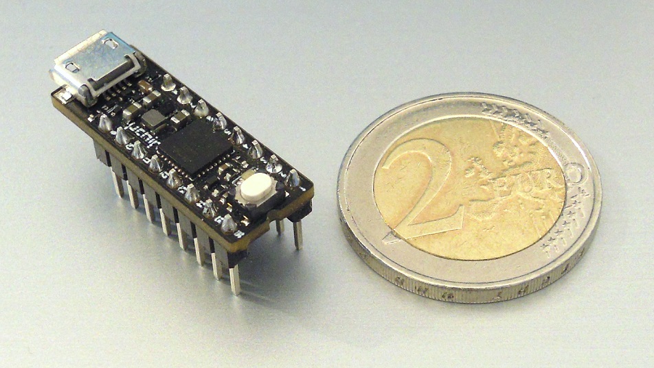
It has the same specs of the Arduino Zero, but it is much smaller, not considering it is also cheaper than an original Arduino Zero (yes, you can buy counterfeit Arduino Zero for 10$ in AliExpress… but we like to stick to original one) . This will allow us to make a small hand held console. You can adapt this project with almost no effort to Arduino Zero. You’ll just have a bulky result though.
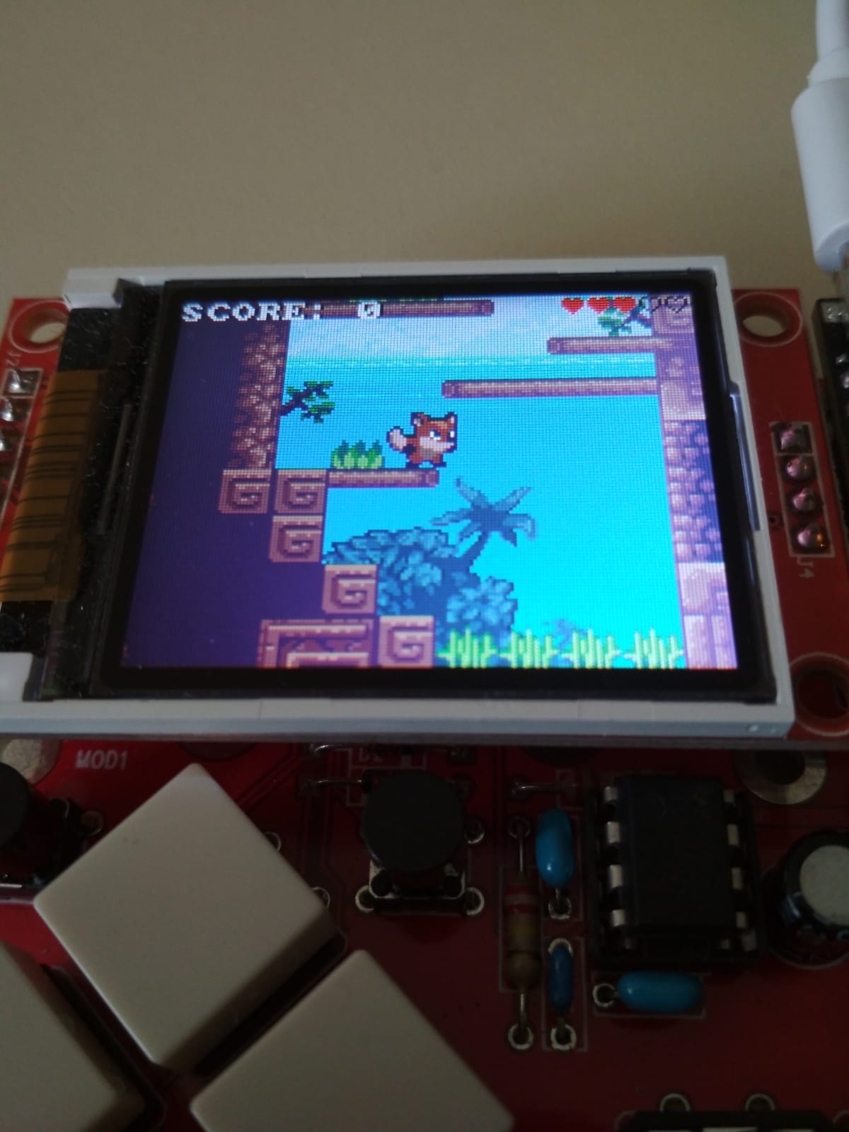
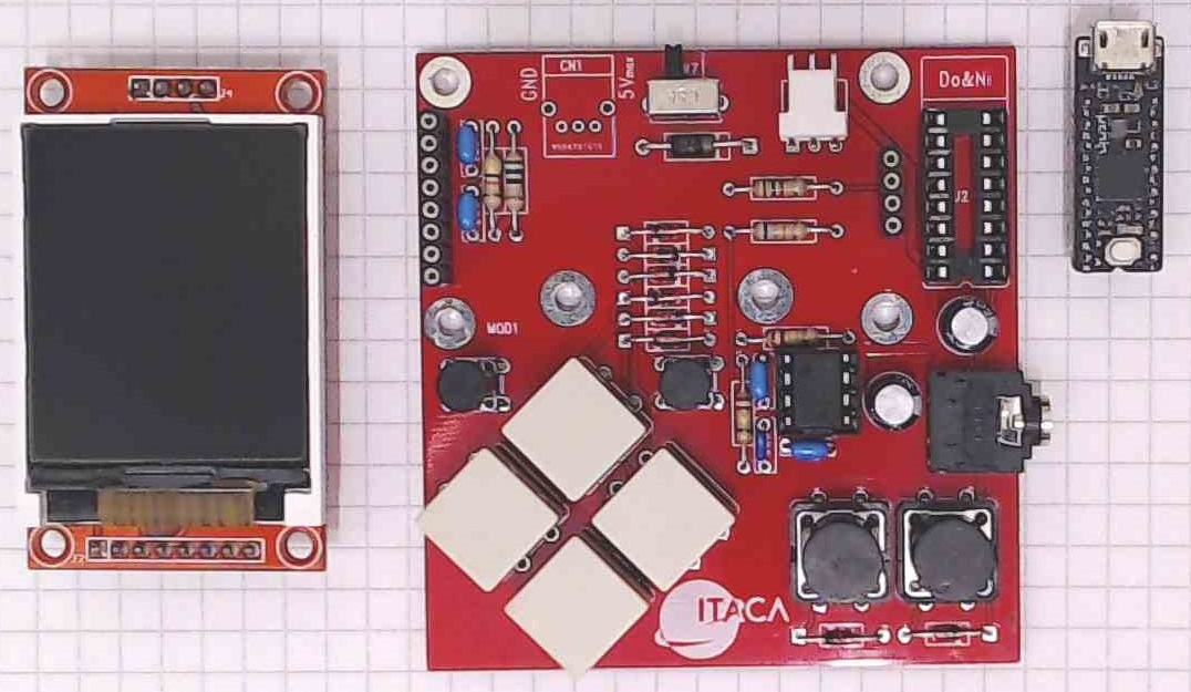
We also created a small test board, which implements a poor man’s hand held console. Details are shown below!
We won’t be using the Arduino framework though. It’s not well suited when it comes to optimization and hardware control. (And let’s not talk about the IDE!)
In this series, we will see how we arrived to the final version of the current game, and we will describe all the optimization and the criteria we used. The game itself is not finished, and it lacks sound, levels, etc. However this can be still used as a starting point for many types of game!
Furthermore, there is room for a lot of optimization, even without assembly!
So, let’s start our journey!
Challenges
There are essentially two challenges on this project. Timing and memory (both RAM and storage).
Memory
Let’s consider the memory first.
First of all, instead of storing a huge picture of the level, we will use tiles. In fact, if you closely analyze most of the platform games, you’ll notice that these are made of a small quantity of graphics element (tiles) repeated many times.
The world/level appears as varied because of the different tile combinations. This saves a lot of storage memory, but it does not solve the problem of the huge frame buffer.
The second trick we will be using is that our uC has both a quite amount of processing power and it has DMA too! Therefore, instead of storing all the frame data in RAM (why should we, anyway?), we will be create the scene from scratch each frame. In particular we will still use buffers, but just large enough to contain a single 16-pixel tall horizontal block of graphics data.
Timing – CPU
When an engineer has to make something, the first step is to check if something is feasible. Of course, we did this check at the beginning!
Well, we want at least 25 fps on a 160×128 pixel display. This means 512000 pixels/s. Since our microcontroller runs at 48 MHz, we have at least 93 clock cycles per pixel. This amount of cycles reduces to 58 if we want to go at 40 fps.
Actually, our microcontroller can handle up to 2 pixels per time, because each pixel is 16 bit, but the ATSAMD21 has a 32 bit internal bus, so the figures could be better!
93 clock cycles per pixel suggests us that actually the task is quite feasible! In fact, we might also conclude that the CPU alone might be enough to perform all the drawing tasks, without DMA. This is probably true, especially with assembly. However, the code would be extremely difficult to handle. And in C it should be very optimized! A Cortex M0+, in fact, is not as C-friendly as a Cortex M3, and it lacks many instructions (even load/store with post/pre increment/decrement are missing!), which have to be implemented with two or more simpler ones.
Let’s check what we need to do, to draw the two playfields (assuming we already know the x and y coordinates, etc).
- Compute the location of the foreground pixel in the flash memory.
- Get the pixel value.
- If it is transparent, then compute the position of the background pixel in the flash memory.
- Get the pixel value.
- Compute the destination location.
- Store the pixel in the buffer.
Furthermore, these operations must be performed for each sprite that might appear in the buffer:
- Compute the position of the sprite pixel in the flash memory.
- Get the pixel value.
- If it is not transparent, then compute the location of the destination buffer.
- Store the pixel in the buffer.
Not only all these operations are not implemented as a single ASM instruction, but also, each ASM instruction takes two cycles when accessing RAM/Flash memory.
Moreover, we are also missing game logic (which, luckily takes a negligible amount of time as they are calculated once per frame), collision detection, buffer handling, and the instructions needed to send the data via SPI.
For instance, here is what we would have to do in pseudo code (assuming no scrolling and a fixed color background playfield for now!) just for the foreground.
Let cameraY and cameraX be the coordinates of the top left corner of the display in the game world.
Let xTilepos and yTilepos be the position of the current tile in the map.
xTilepos = cameraX / 16;       // this is  a rightward shift of 4 bits.
yTilepos = cameraY / 16;
destBufferAddress = &buffer[0][0];
for tile = 0...9
    nTile = gameMap[yTilepos][xTilepos];
    tileDataAddress = &tileData[nTile];
    xTilepos = xTilepos + 1;
    for y = 0…15
        for x = 0…15
            pixel = *tileDataAddress;
            tileDataAddress  = tileDataAddress  + 1;
            *destBufferAddress = pixel;
            destBufferAddress = destBufferAddress + 1;
        next
        destBufferAddress = destBufferAddress + 144;     // point to next row
    next
    destBufferAddress = destBufferAddress – ( 160 * 16  - 16);  // now point to the position where the next tile will be saved.
next
The number of instructions for 2560 pixels (160 x 16) is about 16k, i.e. 6 per pixel. Actually one could draw two pixels at once. This halves the effective number of instructions per pixel, so the number of high-level instructions per pixel is about 3. However, some of these high-level instructions will either be split in two or more assembly instructions, or they will require at least two cycles to complete, because they access to the memory. We are also not considering CPU pipeline flush due to jump, and wait states for the flash memory. Yes, we might be far from the 58-93 available cycles, but we must count the background playfield and the sprites.
Although this shows that it is feasible even with only the CPU, we will see that DMA is much faster. This leaves more room for more on-screen sprites or better graphics effects (we could implement alpha blending for instance).
We will see that the number of C instructions required to set-up the DMA for each tile is less than 100, i.e., we need less than 0.5 instructions per pixel! Of course, DMA still has to perform the same number of memory transfer, but the address increment and the transfer is done without any CPU intervention, which is therefore free to do something else (e.g. computing and drawing sprites).
Using the SysTick timer, we found that the time required to setup the DMA for an entire block, and then waiting for the DMA to finish, is about 12k clock cycles. Please note: clock Cycles! Not high level instructions! The number of cycles is rather high for only 2560 pixels, i.e. 1280 32-bit words. In fact we get about 10 cycles per 32-bit word. However, one should take into account the time required to set up the DMA, and also the time required by the DMA to load from RAM the transfer descriptors (which essentially contain the pointers and number of bytes to transfer). Furthermore, there is always some sort of memory bus arbitration (to avoid starving the CPU), and the Flash memory requires at least one wait state.
Timing – SPI
The other bottleneck is the SPI. Is 12 MHz fast enough for 25 fps ? The answer is yes: 12 MHz corresponds to about 36 frames per second. If we use 24 MHz, then the limit would be two times as large!
By the way, the datasheets of the display and the microcontroller show a maximum SPI speed of 15 and 12 MHz, respectively. We actually tested that these can be pushed to 24 MHz with no problem, at least in the “direction” (the microcontroller writes to the display) we want.
We will use a popular 1.8
inch SPI display. We verified that both ILI9163 and ST7735 work fine (at least
at 12 MHz. The ST7735 is confirmed to work at up to 24 MHz). If you want to use
the same display of the tutorial “how to play a video on Arduino Uno”,
we suggest to modify it, if later you want to add SD support.
We use the version with SD card so that we will have plenty of space for other
things such as audio or additional levels.
The graphics
As we said we will use tiles. Each level will consists of tiles repeated according to a table, which we will call “gameMap”.
How big will be each tile?
The size of each tile has strong impact on the memory consumption, details, and flexibility (and later we will see speed too).
Too large tiles will require to make a new tile for each small variation we would like to have. This would eat up storage memory.
However fewer tiles per screen would be required, increasing speed (see later) and reducing the map size (i.e. number of rows and columns in the table) for each level.
Too small tiles would create the opposite problem. Bigger map tables, and lower speed.
Of course, we won’t be using silly choices like using tiles of 17×31 pixels. Powers of two are always your friend!
16×16 pixels is almost a golden rule, it is used in many games, and this is what we will be using!
Our screen is 160×128. In other words, we need 10×8 tiles per screen, i.e. 80 entries in our table. A huge level, with 10×10 screens (or 100×1 screens), will require only 8000 entries (16 kB if we use 16 bit per entry. We will show you later why we are going to use 16 bit per entry).
Let’s compare this with the amount of memory we would likely use if we stored a big picture of the entire screen: 40k*100= 4MB! That’s insane!
Let’s talk about the drawing system!
Each frame will need to contain (in order of drawing):
- background graphics (back playfield)
- the actual level graphics (foreground).
- the sprites
- text/top overlay.
In particular, we will perform sequentially these operations:
- drawing background + foreground (tiles)
- drawing semitransparent tiles + sprites+ top overlay
- sending the data via SPI.
Background and completely opaque tiles will be drawn by DMA. A completely opaque tile is a tile in which there are no transparent pixels.
Partially transparent tiles, sprites and overlay cannot be efficiently drawn by DMA. In fact, the DMA system of the ATSAMD21 merely copies the data, and unlike Amiga’s Blitter, it does not check for transparency (which is determined by the color value).
All this partially transparent stuff will be drawn by the CPU.
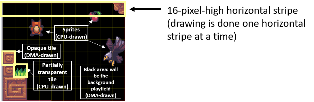
Finally, data is sent to the display using DMA.
Pipelining
As you might see, if we performed these operation in sequence on the same buffer, we would waste a lot of time. In fact, when the DMA is working, the CPU would not be doing anything, except for waiting that DMA has finished doing its job! This is not a good way to implement a graphic engine! Furthermore, when the DMA sends data to the SPI unit, it does not exploit its full bandwidth. In fact, even when the SPI works at 24 MHz, data is sent only with a frequency of 3 MHz, whch is a rather low figure. In other words, the DMA is under used: the DMA could perform other tasks without losing too much in terms of performance.
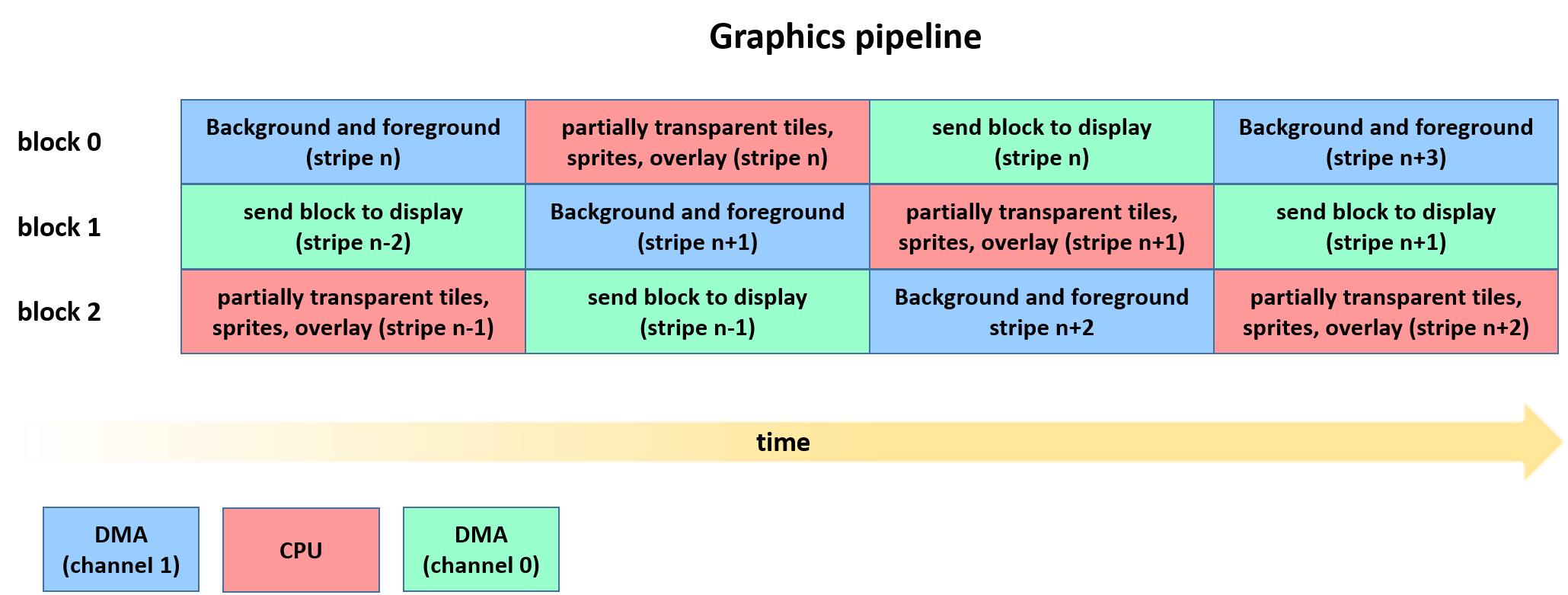
That’s why we implement a pipeline, which is an extension of the double buffering (actually we use three buffers!). Of course, at the end the operations are always performed in sequence. But at the same time the CPU and DMA perform different tasks, without interfering (too much) each other.
We use in fact three buffers, we will call block.
At the same time:
- a buffer is used to draw background data using the DMA channel 1;
- in another buffer (which was previously filled with the background data) the CPU draws sprites and partially transparent tiles;
- finally, another buffer (which now contains a complete horizontal block of data) is used to send the data to the display via SPI, using the DMA channel 0. Of course, the buffer used to send data to the SPI was previously filled with the sprites, while the SPI was sending the previous block, and while the other buffer was being filled with tiles.
The DMA
The ATSAMD21 DMA system cannot be compared to a blitter, but it still has some useful features. Thanks to the DMA, we can have a very high refresh rate, despite the presence of a dual playfield.
The DMA transfer configuration is stored in RAM, in “DMA descriptors”, which tell the DMA how and from where to where it should perform the current transfer. These descriptors can be linked together: if the link is present (i.e. no null pointer), the DMA will automatically fetch a new descriptor, once the transfer is complete. By using many descriptors, the DMA can perform “complex transfers”, which is useful when, for instance, the source buffer is a sequence of non contiguous segments of contiguous bytes. The fetch and write back of the descriptors, however, takes time, as it must save/load 16 descriptor bytes from the RAM.
The DMA can handle different data widths: bytes, half-words (16 bits) and words (32 bits). The datasheet calls this width as “beat size”. For the SPI, we are forced to use byte transfers (even if the current REVD datasheet states that ATSAMD21’s SERCOMs have FIFOs – which Microchip claims they accept also 32-bit data -, it seems that actually it has no FIFO. The REVD datasheet also refers to a SERCOM CTRLC register, which is then missing both on the header files, and on the register description section. Luckily, unlike AVR, ATSAMD21 has at least a buffered transmit data register, so there won’t be transfer gap during send!). To draw the tiles we surely use 32 bits. This allows to copy two pixels per beat. The ATSAMD21’s DMA also permits to increase the source or destination address each beat, by a fixed number of beat sizes.
These two aspects are very important, and they will determine how we draw the tiles.
First of all, if we drew only one pixel per beat (16 bit), we would halve the bandwidth of our system. We cannot renounce to the full bandwidth!
However, if we draw two pixels per beat, the playfield could be only scrolled by an even number of pixels, and this would not appear as a fluid motion. To overcome this, we could use a buffer which is two pixels or more larger. When we send the data to the display, we would use the correct offset (0 or 1 pixel) depending if we need to move the “camera” of an even or odd number of pixels.
However, for sake of simplicity we will reserve room for 11 entire tiles (160 + 16 pixel) instead of only 160+2 pixels. This has one big advantage: we will not need to calculate and update the destination address of each DMA descriptor (this would require several instructions, which might add too much overhead per tile). Of course, we will only draw the minimum number of pixels, i.e. at most 162. Yes, at the end this will waste some memory (about 1500 bytes, considering three buffers), for sake of speed and simplicity. Further optimization can be still performed.

In the animated GIF above, you see all the 16 line buffers (without descriptors) of a block. On the right there is what will actually appear on the display. The GIF shows the first 32 frames, when you move rightward by 1 pixel each frame. The black portion of the buffer is the part that it is not updated, and its content is just leftover from previous operations. When the screen is scrolled by an odd amount of frames, a 162-pixel wide is drawn on the buffer. However, of these, the first and the last column (which are highlighted in the animation) are discarded. When the scroll amount is a multiple of 16 pixels, the drawing operations on the buffer start back at the first column (x = 0).
What about vertical scrolling?
This must be dealt after we show you how tiles are stored in the flash memory.
How to store tiles
A naïve way (which would be OK if you used CPU-only drawing) to store tiles in the flash, is like a sequence of pixel colors. The first pixel of the first row, the second, etc… until the 16th. Then you store the first pixel of the second row, the second, and so on.
Why is this naïve? Because in this way DMA could draw only 16 pixels for each DMA descriptor! Therefore you would need 16 descriptors, which would require each one to make 4+4 memory accesses (that is to transfer 32 bytes – 8 memory read + 8 memory write, the DMA has to perform other 4 reads + 4 writes). This is rather inefficient!
In fact, for each descriptor, the DMA can increment only by a fixed amount of words the source address and destination address. After the first row of the tile has been copied to the buffer, the destination address should be incremented not by 1 word, but by an amount so that it points to the next buffer row. This is not possible, because each transfer descriptor only specifies the beat-transfer increment, which cannot be changed.
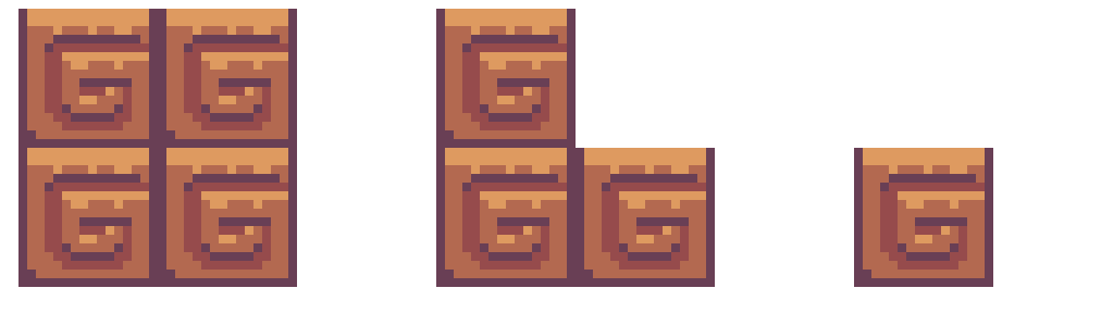
A much more smart way is to send the first two pixels of each row of the tile, in sequence, that is, pixel 0 and 1 of row 0, pixels 0 and 1 of row 1, etc, until pixels 0 and 1 of row 15. Then we send pixel 2 and 3 of row 0, and so on.
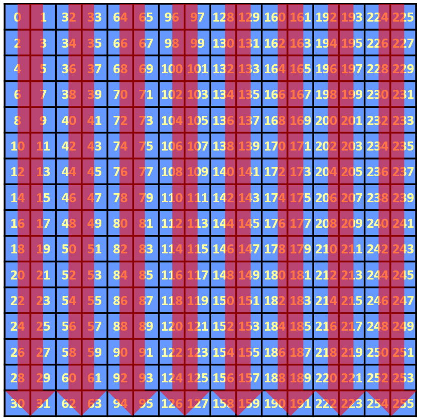
In the figure above, each number indicates the order on which the 16-bit pixel is saved on the tile array.
This can be done using one descriptor, but we need two things:
- The tiles must be stored so that, by incrementing the source by one word, we point always to the correct pixel positions. In other words, if (r,c) is the pixel at row r and column c, we need to store, consecutively pixels: (0,0)(0,1)(1,0)(1,1)(2,0)(2,1)… (15,0)(15,1)(0,2)(0,3)(1,2)(1,3)…
- The buffer should be 256 pixels wide (and not only 160)
The first is very simple to achieve: it’s just a matter of reordering the data, it can be done when exporting the graphics to a c file (see previous picture).
The second one can be achieved because the DMA allows to increase the destination address, after each beat, of 512 bytes. This has two consequences.
- We cannot send using a single descriptor, the entire block via SPI. This is not a huge problem, because after all we just read one descriptor after 160 pixels. The impact will be minimal.
- A block will be 256 * 2 * 16 bytes = 8kB large, and there will be a lot of “unused space”.
The unused space, however, can be still used, for examples, for the descriptors.
In fact each descriptor is 16 bytes large. We need at least 10 * 8 (actually we need 11 * 8!) descriptors for the tiles, and 16 descriptors for the SPI.
Here’s why larger tiles would lead to faster speed. In fact, if we used, for instance, a 32 x 32 tile, we would need less descriptors per screen (320 instead of 640). This would reduce overhead.
Display data block
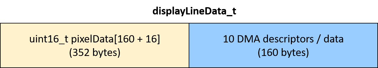
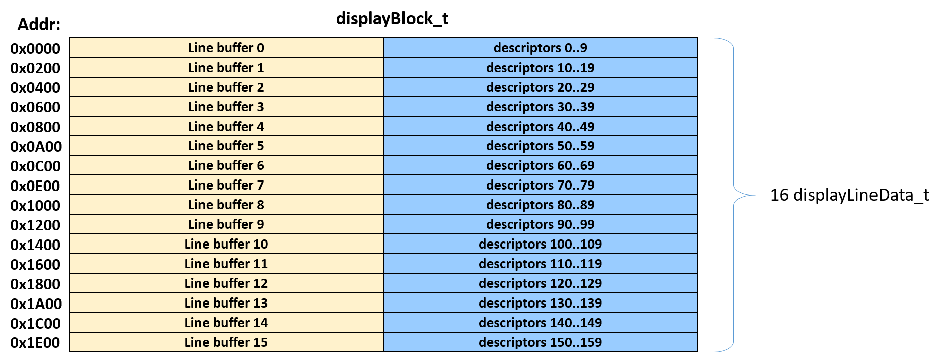
The block buffer, the descriptors and other data are stored in a structure type we called displayBlock_t.
A displayBlock is an array of 16 displayLineData_t. The displayLine data contains 176 pixels, plus 80 words. In these 80 words we store display descriptors, or other useful display data (using a union).
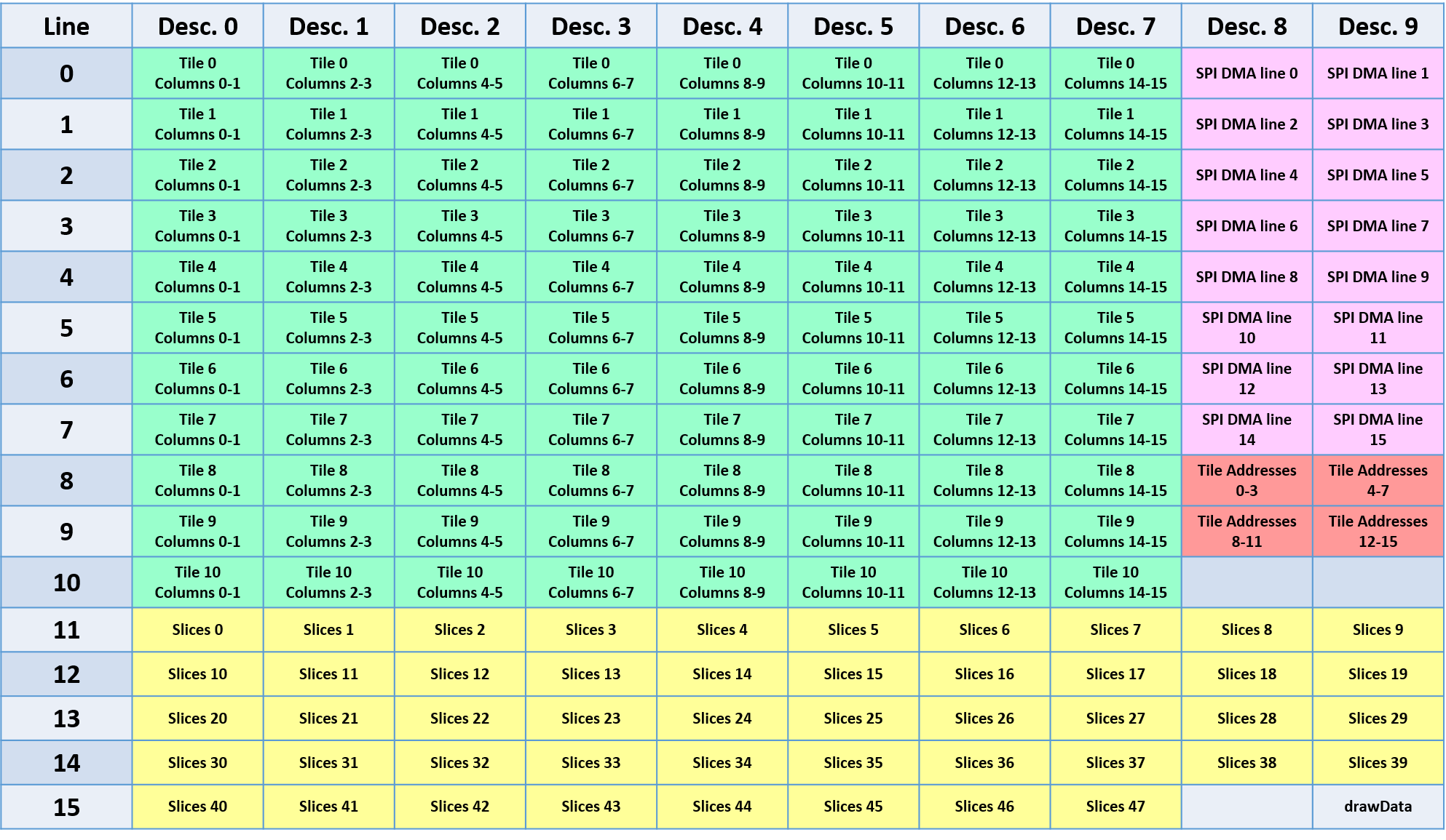
Since there are 16 lines, each tile in position X uses the first 8 DMA descriptors (0 to 7) of lines X. Since we have at most 11 tiles (hence the 176 pixel wide display line), the tiles only uses the DMA descriptors of the first 11 data lines. Descriptors 8-9 of all the lines, and descriptors 0 to 9 of lines 11-15 are free.
Of these, descriptors 8 and 9 of lines 0..7 will be used for the SPI.
The descriptors 0..9 of lines 11-15 (up to 50 descriptors, even though we will use only 48 of them) will be used for the background playfield.
The picture below shows its organization.
The background playfield
The background playfield is treated differently. First, we must renounce to the two-pixel alignment, if we want smooth scrolling. This is because the foreground and background scrolls at different speeds. Therefore beats will be half-word large. Even if this has some drawback in terms of speed, this allows an easier integration. Since there is quite a small number of descriptors left, we can’t use small tiles. Furthermore, to simplify everything and to quickly add parallax, we will use long “slices”.
Background is actually drawn only if there is at least one partially transparent pixel. This means that if there is just a single transparent tile, the background will be drawn. This is of course a waste of bandwidth, but it simplifies everything.
If we compare the background to foreground playfield:
- The background uses slices, which are long tiles, stored in the “naïve” way.
- The background has its own map, which however is repeated horizontally. In this way, less memory is used.
- The background has per-slice parallax.
The foreground playfield
As we said, we have on each block, up to 11 tiles (10 full tiles, or 9 full tiles and 2 partial tiles). Each of these tiles is drawn by the DMA only if it is not marked as transparent. Instead, if they are not completely opaque, they are added to a list, which will be analyzed later, when sprites are drawn.
Putting together the two playfields
The descriptors of the background playlist (which are always calculated) and those of the foreground playfield form a very long linked list. The first part draws the background playfield. The second part draws the tiles, over the background. The length of the latter part might be variable, as the DMA descriptors of partially transparent tiles are excluded from the list. If a block contains only opaque tiles, then the DMA is set up so that it starts directly from the first descriptor of the first tile.
Sprites and transparent tiles
Transparent tiles and sprites are treated almost at the same way. The pixel of the tile/sprite is analyzed. If it is black, then it is transparent, therefore the background tile is not changed. Instead, if it is not black, the background pixel is replaced with that one of the sprite/tile.
Vertical scrolling
When dealing with horizontal scrolling, we draw up to 11 tiles, even if, when drawing 11 tiles, the first and the last will be only drawn partially. This partial drawing is possible because each descriptor draws two columns of a tile, therefore we can easily set where to start and stop our linked list.
Instead, when dealing with vertical scrolling, we should compute both the destination register and the transfer count. This should set multiple times per frame. To avoid this hassle, we will simply draw up to 9 complete blocks per frame (just 8 when the scroll is a multiple of 16).
Hardware
As we said, uChip is the heart. What about the other things?
Here is the schematics! There are some aspects about it that are worthy of discussion.
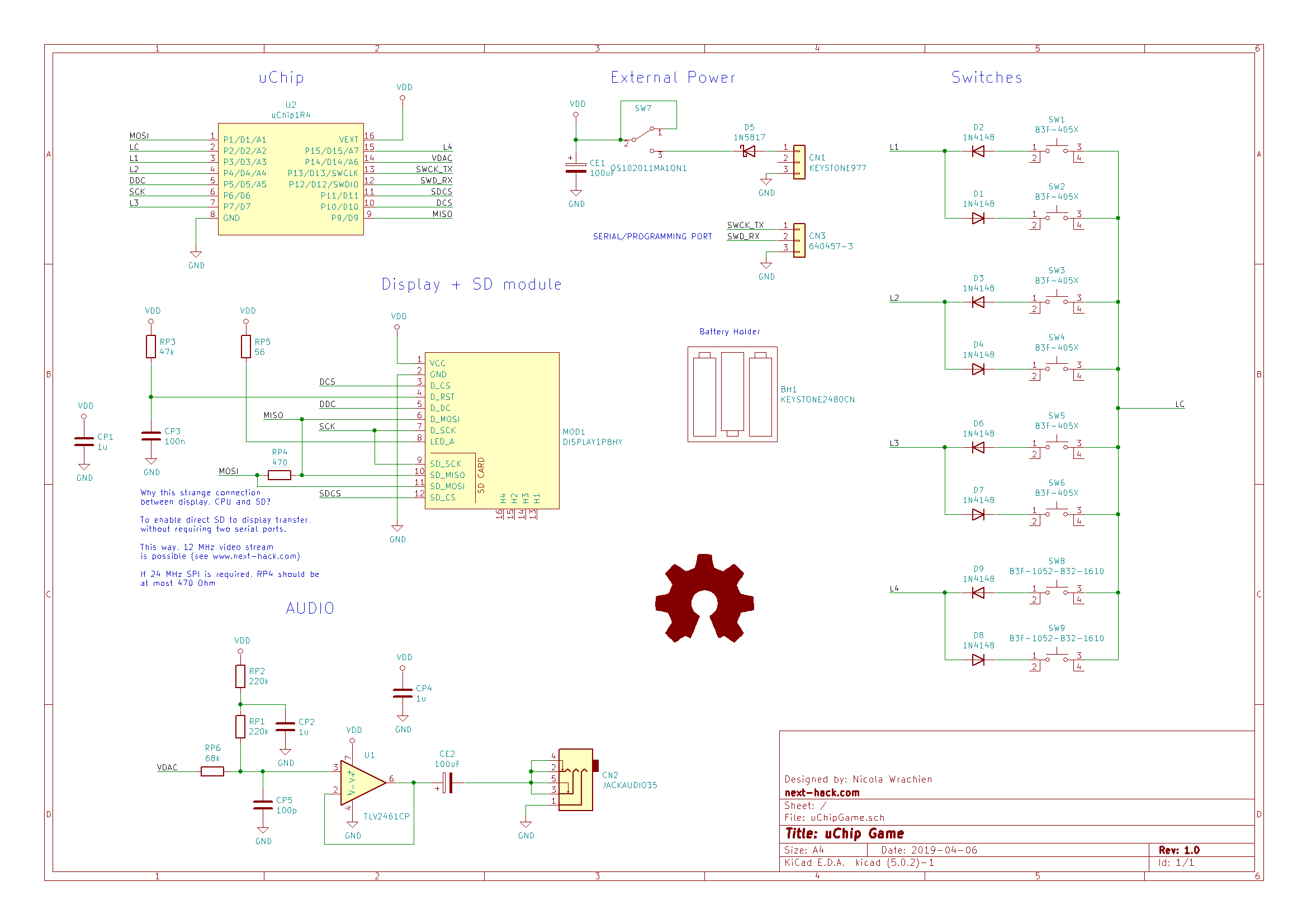
Keys
To optimize I/O usage, we use a small trick. There will be 4 sensing lines, L1-L4, and one common wire LC. The common wire will be alternatively set to 1 and 0. The sensing lines will be alternatively pulled low or high, respectively, using the internal pull-up/down resistors. Two keys are connected between each key line and the common line. In series to these two keys, a diode is inserted. Each of these diode has the opposite polarity, so that only one key can be effectively “sensed” each time.
Since there is no built in
keyboard controller (and since no embedded keyboard controller use this
peculiar method), the eight keys are quickly sensed at the beginning of each
frame. Since the inputs must be both pulled up and down, we cannot use (and we don’t
even want to) external resistors, so we must use the integrated resistors,
which might be quite high valued (60 kOhm). This means that, when the common
line changes state, and the sensing lines change their pull up/down state, one
should insert some delay, to allow the integrated pull up/down resistor
charging the pin and track parasitic capacitance to the desired level.
However we do not want to wait! Therefore we set the common line to a high
impedance state (so that no contentions occur), and we precharge the sensing
lines to a logic value 1 or 0, by temporarily configuring them as output.
Later, they are configured as input with pull-up or down respectively. Since
the output resistance is in the order of few tens of ohm, the state is forced
in few ns, therefore, when the sensing line is configured back to input, it
will be already at the right state. After that, the common line is set to
output with the opposite polarity.
This drastically increases the scanning speed and no delays/nop are requested.
SPI connection
We connected the SD and the display so that they can communicate each other without the data actually going to the ATSAMD21. This might be useful if you want to play a video.
The resistors that connects MISO and MOSI should be low valued. In fact if it is too high, the SPI will not work, as the signal will be too much degraded.
Optimizations and further developments
One of the biggest issue is the RAM usage. The three blocks take 8 kB each, leaving only 8 kB for stack, and the other variables. As for now, we have only 1.3 kB of free RAM + 4 kB of Stack (4 kB of stack is very large, we might reduce it).
However, we could consider 8-pixel tall blocks, and not 16. This would increase the overhead for the DMA descriptors, but it would cut almost by half the memory usage for the block buffer (note that the number of descriptors would not change, if we still used 16×16-pixel tiles, therefore we would need to change the block organization). This could free about 7.5kB of RAM, which could be very useful, to easily implement some features, like variable map with secrets, or add audio (though Audio could be still easily added even with as low as 1kB of RAM).
Another issue is the sprite, but this modification is much easier, and it only involves the function createNextFrameScene(). In fact, we create a huge array in RAM with the state of all the sprites. For each sprite, we then calculate if their position is within the display area, and then we animate and add them to the draw list.
We could instead perform some kind of optimization. For instance, in the gameMap we not only store the tile value, but also a flag indicating the transparency of the tile, which is determined by the Editor. This allows us to quickly check if the tile must be drawn by DMA or CPU. That’s why we use 16-bit entries for the tile map. Assuming a 256 tile-set (currently we have less than 128 tiles, but there is enough room in the flash to add some more), we have still 7 bits available, for other purposes. Three of these 7 bits could be used to indicate if there is stored any sprite/object. For instance:
0b000 = no stored object
0b001 = opossum
0b010 = eagle
0b011 = frog
0b100 = gem
0b101 = cherry
0b110 = switch
0b111 = other future things, like secret walls that disappear.
Then, we could create a bitmap table in RAM, in which each bit indicates if the item has not been discovered (for instance an enemy) or if it not has been picked up (e.g. bonus), or not activated (switch). In a 10×10-screen level, we would need 8000 bits, i.e. 1kB of RAM. The bit is cleared when the enemy has been discovered, or the bonus has been picked up.
In the createNextFrameScene() we would check the bits corresponding to the tiles in the current view area. If these are at 1:
- If these are bonus, simply add them to the sprite list to be drawn.
- If these are enemies, create a dynamic sprite, and clear the flag. Next frame scene will still contain this dynamic sprite, until the enemy goes off-screen, or it has been killed.
This has some drawbacks.
- The first one is that the sprites must be aligned at the tile boundaries, when it is created (then it is free to move with sub pixel precision). This is not a big issue, though.
- The second one, is that we always need to check all the 80 screen tiles, to check which sprite we need to draw. A much clever solution would be to check the bitmap table, because with one access we get 32 tiles at once. Still this would be an issue for switches/objects that may have an on/off state (they should be drawn even in off position, i.e. when their flag in the bitmap table is 0!). The solution would be to draw always the tile in off-state and then have a sprite (which has the exact size of the tile and it is completely opaque) drawn over that tile, in on state.
- The third one is that we need to create a dynamic list of sprites. If one manages to get followed by many enemies (without killing them) the list could become huge. Furthermore dynamic lists are always somewhat difficult to handle.
- The fourth one is that one could cheat, by first discovering an enemy, then having it becoming off-screen. A partial workaround would be to store in the dynamic sprite data the tile position where it was born. If it goes offscreen, and it has not been killed, we could set again the bit corresponding to the tile it belong, so that if the player goes back, the enemy is back again!
- This technique cannot be efficiently used when all the characters must be “live” even if off-screen (e.g. like a top-view version of Unreal Tournaments, where the bots must continuously fight each other).
However, in this way we could much more efficiently store and handle a lot of sprites in the level.
Still, this technique is more related to the “game logic” part of the game, rather than the graphics engine!
We might implement later this feature.
Hey, you are saying that you are using 16 bits per pixel!
But I do not see 65536 colors onscreen!
Yes, for two reasons.
The first one is that the original tile set did not use 65536 colors. Yes, the original color space was 24 bits, but not every RGB combination was used! Probably the original author (ansimuz) optimized the tileset for a 256 on-screen palette (actually we did not perform a color count!). Had the tileset been in black and white, you woud have seen just 2 colors, despite the 16-bit graphics operations! You are free (and encouraged too!) to change the graphics, and achieve more onscreen colors: this article is not about the particular pixel art graphics, but rather about the capability of handling and showing 16bpp graphics at 40 fps, with dual playfield, parallax scrolling and onscreen sprites on a Cortex M0+ microcontroller.
The second reason is even simpler: the display has only 20480 pixels so at any time you’ll at most see 20480 different colors onscreen. Unless bizarre color combinations are choosen, you’ll never see that many different onscreen colors from a 16 bit palette… Still, this does not mean that, in the whole level, you won’t be able to see all the 65536 colors (that would be still very difficult to achieve, but only from an artistic viewpoint).
Summary
We hoped you enjoyed this introduction. There are still a lot of things we should and would explain. These will be the subject of future articles.
In the meantime, you can download the full source code of the game! Please if you enjoyed it, consider of making a donation to ansimuz, who is the artist that drew all the graphics and donated it to the worlds, for free! We won’t reject donations either 🙂
The game is not complete yet. We still want to add audio, multiple levels, objects to interact with, etc. Feel free to make your own modifications! We hope to see new games with new graphics and levels!
The map editor will be released soon. It’s too rudimental for now to be released to the public!
Video
(Note! The video is taken at a much lower frame rate, due to poor ambient illumination! We will update the video very soon, to make you appreciate the full 40 fps speed!)
Credits
The graphics of the game (and of the tiles shown in some of the images above) comes from the “Sunny Land free asset” by ansimuz.
Downloads
Please note that this project is open source. As such, it is provided for free (even though we will not be angry if you wanted to make us a donation to show your appreciation!). It is shared in the hope you will find it useful. We also make no guarantee your house/city/country/planet won’t explode due to some bug/mistake, which might be present in the code!
Atmel Studio 7 project (sources)
Nice job Bro,thx for your help
Thanks man!
great achievement … i enjoyed reading through the details … cant wait for the next installments … have u thought abt 8 bit color pallet instead of 16 bit for each pixel ? i think 256 colors is more than enough for retro style games.
Hi! thank you!
The 16-bit per pixel depth was chosen because in this way we can use DMA (no need to translate the 8 bit LUT to 16 bit!) 🙂
But definitely, for the sprite (which must be drawn by CPU) we could use a 256 color palette and save a ton of flash memory! (However, this could still slow down, as you need to perform one more memory access, to translate the 8-bit pixel to 16 bits, instead of just copying the 16-bit pixel to the buffer).
does it run in parallel to playing sound ?
Hi! At the moment sound is not implemented. It will be implemented soon. We plan to make some changes in the PCB so that SD (where sound fx and music will be stored) can be accessed with a separate SPI!
I’m working with an atmega32u (or something along those lines) and an old Nokia screen in c. Seeing this gets me excited for my own project. Really impressive work. This is now something I aspire for although my game has such little meat compared to this, it’s barely a skeleton. This is to cool!!!
Thanks to the author! I repeated the project, everything works fine. The author helped me with assembly and programming.
Great article. Please share more tutorials. The wealth of your knowledge is impressed and even more your talent to share it. Thank you.