
Index
- Introduction
- Installation
- What it is and What is not uChip Game Map Editor
- The uSVC Palette and a Graphics Editor Suggestion
- The Tiles
- The Map Editor
- Choosing a Tile or Block of Tiles
- Placing a Tile or Block of Tiles
- Filling a Zone with a Tile or Block of Tiles
- Selecting a Tile or Block from the Map
- Saving and Loading the Map
- Exporting the Map to C Files
- Exporting Tile Graphics to C Files
- Sprites
- Placing Sprites in the Map
- Loading and Saving Sprite Positions
- Exporting Sprite Data and Positions to C File
- What About the Handheld Platform?
- Source Code and Download
- Conclusion
Introduction
In a previous article, we introduced uSVC, an open source retro game console, based on uChip. In the following posts, we will of course provide you with some tutorials but, before them, we need to introduce an important tool, which will be used extensively to create our games.
This tool is uChip Game Map Editor, a free, open source, java-based (hence multi-platform) editor for uSVC. This editor was once developed to build the hand held console shown in this article, and it has since been improved to support uSVC too.
Note! the game editor is not optimized, and a good code clean-up would be required too!
Installation
Since uChip Game Map Editor is programmed in Java you need to download and install JDK from here: https://jdk.java.net/14/. Remember to make sure that the PATH environment variable is correctly set.
After this, download and unzip the uChipGameMapEditor archive where you want, and you’re set. To launch the editor, simply double click on uChipGameMapEditorWindows.bat or uChipGameMapEditorMAC.command, for Windows and Mac/Linux, respectively. These files are in the main directory you have just unzipped the archive.
What it is and What is not uChip Game Map Editor
Despite its name, this is not only a map editor, but it contains also other features, such as:
- Place sprite and waypoints.
- Export graphics (sprites and tiles) and audio (wav and midi files) to C files.
- Create and export shade tables for the color remapping engine.
- Create uSVC game package so that it can be loaded by the uSVC Game Loader.
- Other utilities, such as creating precalculated math function tables.
This program, however, does not allow you to create graphics, as it is not a graphics editor. To create graphics, an external program, such as GIMP is required.
The uSVC Palette and a Graphics Editor Suggestion
As a prerequisite, to create graphics you need… graphics, of course, but a very special one. The image you are using should be either 8 bpp (for 8-bit modes) or 4 bpp (for 4 bit modes) and they should use the uSVC palette described below.
The uSVC palette is RGB332, i.e. with 3 bits for red, 3 for green and 2 for blue. For each color, the shades are roughly uniformly distributed. You can download this cvs file to get the exact 256 color values, in RGB 24 – bit format.
To create all the graphics, we used and suggest GIMP, which is available here: https://www.gimp.org/downloads/. It is a very powerful general-purpose graphics editing tool, and can be used for pixel-art too. If you are not used to it, we strongly recommend to watch some tutorials on youtube or read some guides on the web.
When using GIMP, we strongly recommend you to use the custom palette contained in this archive. To import it on GIMP, you can use the method described here https://youtu.be/b7zjj6ry5rs?t=255, at time 4:15, after unzipping the file.
The Tiles
Short description: in the most advanced graphic modes of uSVC, images and level maps are generated by repeating small graphics elements called tiles, each one being 8×8 pixels.
More in detail (you can skip this!):
The most interesting and feature-rich video modes of uSVC are the 8-bits per pixel (8bpp) TILE_MODE1 and 4bpp TILE_MODE2. In these modes, the image is not stored as a sequence of bits/bytes in a large array, but instead, a much smaller table, called video ram, or vram, stores the indexes (actually the lower part of the address) of 8 by 8 pixel graphics elements, called tiles. The drawing routine that generates the VGA signals on-the-fly looks in the vram for the address of the tile corresponding to the particular position we are going to draw. The function adds to this address an offset, based on the vertical and horizontal positions on the tiles, to find which color we need to output[1].
In this way, we can create colorful images using a very little amount of RAM memory: the vram and the RAM to store all the tiles[2]. Of course, this does not come without drawbacks: the image is created with a repeated number of tiles, so it is up to the game/level designer to create a level/map that minimizes the sense of repetitions and regular patterns.
To assist you in the generation of levels or even simple images/menu/etc. the most important feature of this editor is the map editor (hence its name). Most probably you can also use other editors, which might be more advanced, optimized, easier to use (and In some case neither open source nor free…), but you have to make sure that they later allow to export the data in a format suitable to the uSVC kernel.
The map is basically a table in which for each row and column a number Is stored, indicating which tile you want to be there.
In the game, you will need to create a drawMap function, that takes a rectangular portion of the map, and using that data, it fills the vram (i.e. the display) region. Of course we will show you how to create such function, therefore all you have to do is to basically copy that function from our tutorials or example games/demos. You are encouraged to implement a better and/or more optimized version, though!
In this example, we will just talk about level maps, but the exact same procedure can be used to create images (e.g. for title screen), or menus, etc.
To create a level, you first need a set of tiles (tileset hereafter), which includes all the tiles you are going to use in your level. We won’t teach you how to create a good tileset, as this is beyond the scope of this article, and a lot of guides can be found elsewhere, even on youtube.
Note! It might be tempting to create a very huge tileset for your levels. However you have to take into account the RAM limitation. We will talk about this in other posts, but for now try to keep the number of tiles under about 200 and 600 for 8- and 4-bpp modes, respectively. These numberss are just indicatives, and they can be incresed or decreased by trading off the number/size of on-screen sprites.
There are two ways of importing a tile set:
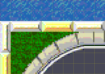
- You have an image, with all the tiles, with an 8×8 pixel alignment.
- You have one or more images, each one containing one or more 8×8 pixel tiles (if there are more than one tile, then they must have 8×8 pixel alignment).
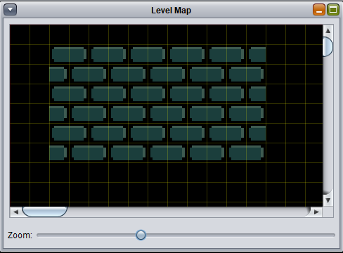
We will cover for now only the first case, which is the most popular one: you have an image (PNG or bmp. NEVER use jpeg!), in which there are all your tiles. The tiles might also be repeated more than once, or even arranged in templates. However, all tiles must be aligned on an 8×8 pixel grid.
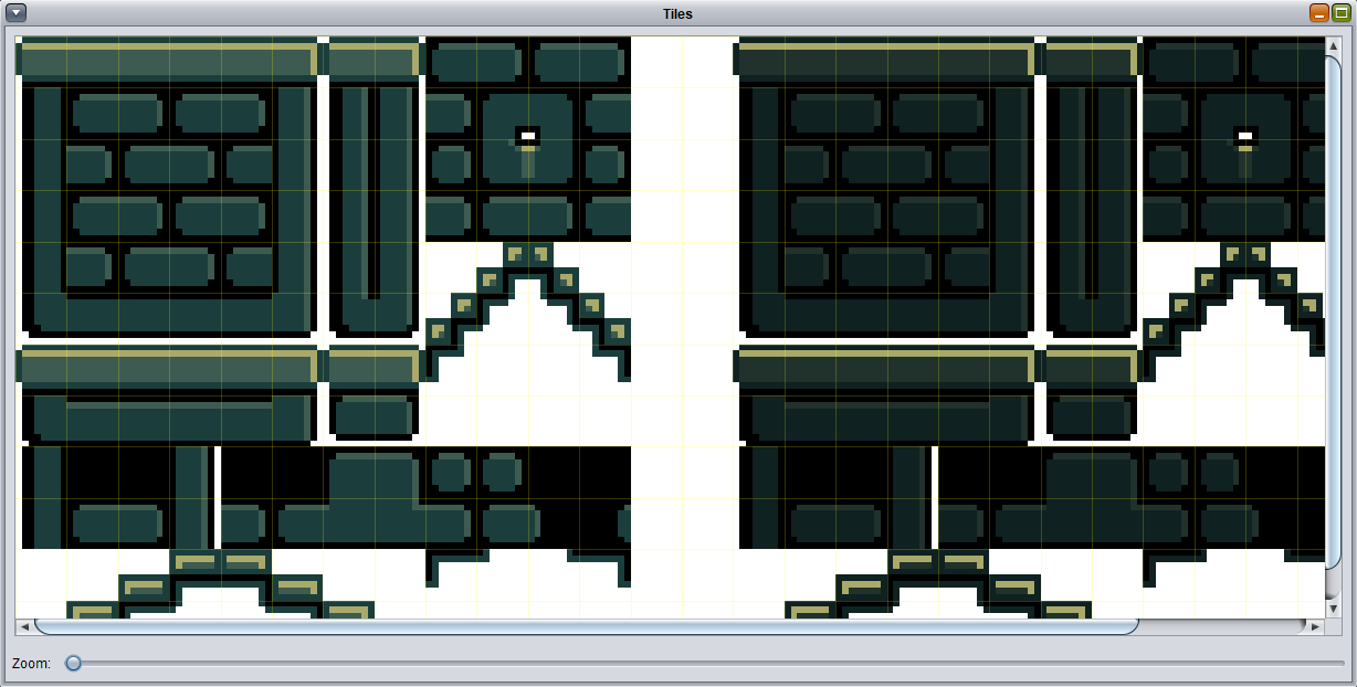
As shown in the figure above, the tiles are pre arranged in several templates (with 8×8 pixel grid alignment). This might mean that some tiles are repeated more than once (indeed, also the white space surrounding the templates is actually a “white” tile repeated several times). This is not a problem, because, when you export the map to a C file, the editor will detect if two tiles taken from two different points of the tileset image are actually the same; in this case, only one copy will be exported, to save memory.
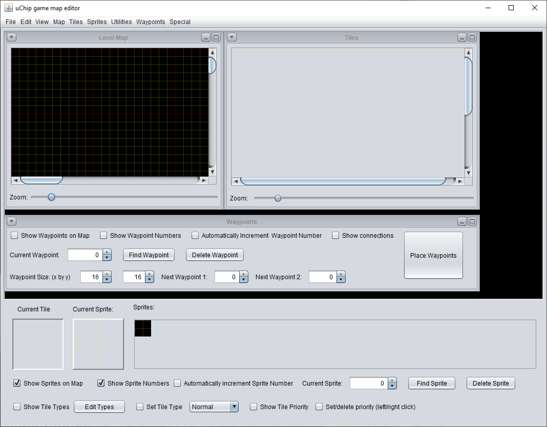
The Map Editor
Note! First make sure that all these items are not selected:
- “Place waypoint” in the waypoints window.
- “Set tile type” (on the bottom part of the main window).
- “Set/delete priority (left/right click” (on the bottom part of the main window).
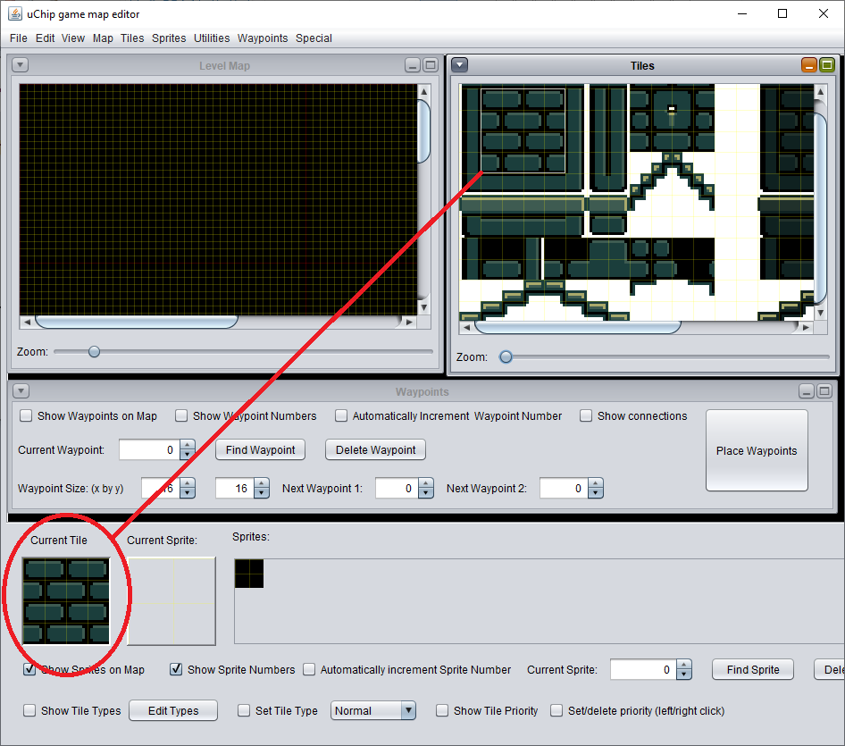
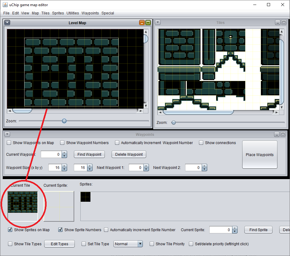
As a first operation, you should load the tile image. Therefore, go to the menu “Tiles” and select “Load Tile Image”, and select your tileset image. The editor has been originally programmed for the handheld game console, which used 16×16 pixel tiles, therefore it will ask you the size of the tile. Set the tile size is 8×8, and confirm. You should see your tile set on the right window (“Tiles” window).
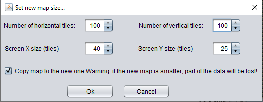
Then you have to set the map size. Therefore, go to menu “Map” and select “set Map and Screen Size”.
A dialog will ask you the size (in tiles) of the map and the screen. A 320×200 screen has 40×25 tiles. Setting the screen size is not required, but it helps you in determine how big your level is. In fact, the editor uses the red color in the grid, to show the screen boundary.
Once you have chosen the desired map size, confirm and you are ready to place the tiles on your map.
Choosing a Tile or Block of Tiles
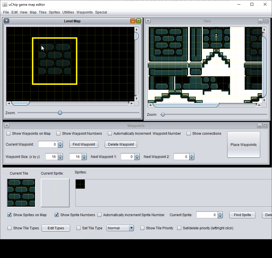
To choose a tile from the tile window, you just have to select it with a left-click on the tile window. You will notice that the “Current Tile” (at the bottom of the main window) has changed to reflect the selected tile. You can also select a block of tiles, by clicking and dragging on the tile window. This latter function helps you to place “templates”, instead of having to put them tile-by-tile. The “Current Tile” panel will now reflect the selected block.
Placing a Tile or Block of Tiles
Move the mouse on the map: if “show tile selection on map” in the “view” menu is selected, you should see the “ghost” image of your tile, which follows the mouse on the map. Left click to put the tile. By holding the left mouse, you can continuously draw the same tile or block.
Filling a Zone with a Tile or Block of Tiles
To fill a rectangular zone with the same tile/block, hold the ctrl-key and click and hold the left mouse button on the map. You should see a rectangle being drawn on the map. Once you release the mouse button, the whole area will be filed with the block/tile shown in “Current Tile”.
Selecting a Tile or Block from the Map
Besides getting templates from the tile window, you can also get tile blocks from the map. To do this, press shift and click and hold the left mouse button. As you move the mouse button, you should see the current tile changing to reflect the selected area. Once you release the mouse button, you will see that now you can place on the map the block you have just selected.
Saving and Loading the Map
The usual “load/save/save as” menu entries are present. We think that there is no need to further explain their functions. The map is saved in JSON format.
Exporting the Map to C Files
Once you are happy with your map, you can export it to C file your map. Note that this is the format that uSVC will interpret, not the format that the editor uses, therefore remember to always save your map, before exporting!
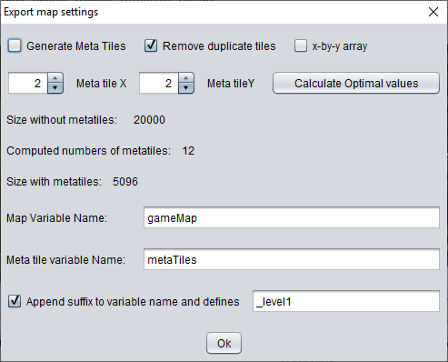
If you click on “File -> Export Map To C File”, the following dialog will appear:
Let’s have a look at the various entries.
- Generate Meta Tiles.
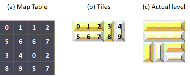
If this option is NOT used (unchecked), then the map is generated as an array of X by Y entries of two bytes. For a map of 100×100 tiles (about 2.5 x 4 screens), this means that 20kB of flash would be used, excluding any graphics data. However, in a very large number of cases, the map itself might be described by repeating some N by M tiles blocks, as shown in the example shown in Fig. 11 below. We call each NxM block as metatile. By exploiting this, we do not have to store 2 bytes for each tile, but only for each N by M tiles, therefore the map size is decreased by NxM.
Note! A large of NxM will decrease the actual number of map entries, but, possibly, there will be many more different metatiles, which must be “described” in a separate array. A smaller value, will reduce the number of different meta tiles, but the map memory occupation will be larger.
Currently, our examples only support 2×2 metatiles, as we found that this is a good tradeoff in terms of map size reduction and performance.
Typically, for non-trivial maps, with a 2×2-metatile, one might expect a 50% reduction of the original size. A careful level design might improve the 50% factor, i.e. by aligning templates on a 2×2-tile grid on the map, and using few templates.
If this option is enabled, metatiles will be enabled, but the draw map function in your game should support them. Please note that drawing a map with metatiles is typically slower, because one has to look at two arrays.
- Meta tile X/Y
These must be power of 2, and indicate the number of horizontal and vertical tiles for each metatile. As said, our examples only used 2×2 metatiles, but you can implement a draw map function, which uses bigger metatiles. - Size with/wihout metatiles.
These parameters show the size (in bytes) the map will have without metatiles, and the size (combined of the map + metaTile description array) using metatiles. There is also an option to calculate the optimal value, in terms of space consumption. - Computed number of metatiles.
The editor scans the map and find the number of different metatiles your map would use with the selected X and Y sizes. - Remove duplicate tiles.
The editor will check if two tiles are the same, and it will assign to them the same tile number. This is to save space later when exporting the tile graphics data. - X by Y array.
The array will be saved as const uint16_t map[HEIGHT][WIDTH] instead of const uint16_t map[HEIGHT * WIDTH]. There is no difference in space occupation. In our example we used the second version, i.e. option unchecked. - Map and meta tile variable names.
These will be the base name of the arrays that will be created in the exported files. - Append suffix to variable name and defines.
This will add the specified suffix to each variable. For instance if you specify _level1, then the map will be created as map_level1, whereas for instance, the horizontal map size will be MAPSIZEX_LEVEL1 (with upper case letters).
Once you press ok, you will be requested to choose the destination file name.
The exported file will be created there. We will have a look at it in the uSVC tutorials.
Exporting Tile Graphics to C Files
We have already exported the map, but we do not have any tile graphics data yet. Here is how to export. From the menu “File” click on “Export Tiles to C file (no duplicate tiles)”.
The following dialog will appear:
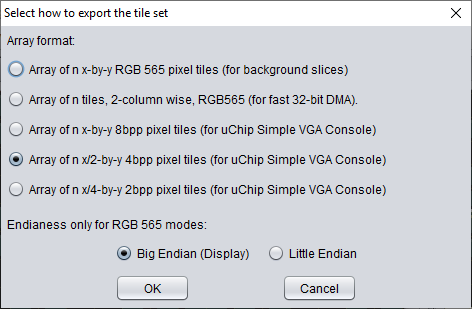
In this window, you just have to choose either 8bpp (third choice) or the 4pp (the fourth). The first two ones were used for the handheld platform game, while the last one (2bpp) is to compact data in flash, when only few colors (4) are used, in the whole tile set (in particular: game loader splash screen). You must select the appropriate number of bpp, depending on how many bpp the original tileset image had.
The endianness is ignored, because it refers only to 65536 color modes. In uSVC data is always little endian i.e. 0x1234 is stored as 0x34 0x12.
After that, you will be asked to enter a file name. Confirm and then you should find your c file in the specified location.
Sprites
Sprites are objects that:
- Can be moved.
- Can appear/disappear.
- Can be animated.
- Can be flipped or mirrored (or even rotated by 90°, 180° and 270° in 8-bit mode).
These are separated from the tiles, and need a different approach.
First, you need a sprite set, i.e. an image where you have placed all the sprite frames. A character/object is defined as “entity” and it can have one or more animations: we suggest (even if this is not mandatory) that you place each animation on a separate row. We also suggest to create your sprite set image so that each animation requires at most one single horizontal slice in your image. The reason of why we suggest this will be clear later.
Moreover, we suggest that you center each animation, and place the frames of each animation at equally spaced intervals. Do not worry about empty space: for each frame, the editor will calculate the smallest rectangle that contains it (i.e. without transparent pixels), and it will also calculate the offsets values used by the sprite engine, so that the sprite will be placed correctly when you call the function putSprite().
Now, you have the sprite set image, how can the editor (and later, your game) understand where is each frame in the image? You must create a sprite set data file. Yes, you can create it by hand, or even using a script, but this might be a very long and error-prone task. Instead, to create this file, we developed a simple utility, which is embedded in the editor.
To open this utility, select “Open Sprite Set Creator” from the “Sprites” menu. A new window will appear. Choose your sprite set image, by clicking on “change sprite set image” on the bottom right corner. Your sprite set image will appear. You will notice that there is a 1-pixel grid superimposed to the image. This helps in choosing the sprite area.
Now that your sprite set image is open, you can start creating your sprite set data file. You have two methods:
- Manual method. You must add, frame by frame the sprite data.
- Semi automatic method. For each animation, you just insert just the data of the first frame (width, height, position), and the editor will get and create all the other frames entries for you.
Let’s discuss the first method. To add a frame, click on “Add” on the bottom left part. An empty entry will appear in the table. Now, you can modify x, y, w, h as well as all the other entries. You can also pick the image from the sprite set image on the right. To do this, make sure that “Get From Image” button is selected, click the table row you want to modify, and click and drag on the sprite set image on the right, to define the rectangle region that contain your sprite frame. Once you release the left mouse button, you’ll see that all the x, y, w, h data have been changed accordingly. You might also zoom to have a better precision.
Remember to change the entity name, animation name, and frame number accordingly!
Note: The combination of entity name, animation name and animation frame number should be unique!
However, this method is quite long and frustrating if you have a large number of frames. The second method strongly speeds up the sprite set data creation. This method requires that:
- Each animation stays in only one horizontal block, and no more than one animation is on the same horizontal line.
- For each animation, the frames are centered and equally spaced.
In this way, for each animation (and not for each frame!) you just have to click on “Add frames”, and fill some data. These data are: “Entity Name”, “Animation Name”, the number of frames, and the size of each frame. (Optionally, if you deselect “after last frame” you can specify the starting position of the animation. We recommend not to deselect this).
Once you press OK, you’ll notice that the editor will fill for you all the details, frame by frame, saving you a lot of work. To check if the frames have been correctly chosen, you can select all the relevant rows on the table, and look at the sprite set image.
Once you’re done, click on save, and use the exact same name of the sprite set image, but change the extension to “.json”.
Now, close the sprite set editor window, and choose from the “sprites” menu, the “load sprite set” entry. Choose the sprite set image, and the editor will pick up also the json you already have created. You should see the first frame of the first animation of each entity on the sprites panel, which is on the bottom part of the editor.
Placing Sprites in the Map
We assume that you have already loaded your sprite set, therefore you’ll see the first frame of the first animation of each entity. To place a sprite, click on one of the entities, and click on the map. Make sure that you “Show Sprites on map” (and “Show sprite number”, if you want to know the sprite index) is checked. You might also want to select “Automatically Increment Sprite Number”, so that each time you click on the map, a new sprite will be allocated. To choose a particular sprite index, select the corresponding value in “Current Sprite”. You might also click on find (The current sprite will be centered), or delete, to remove a sprite.
Loading and Saving Sprite Positions
Sprite positions can be loaded/saved using the corresponding entries from the “Sprites” menu. Please note that you need to load a sprite set first!
Exporting Sprite Data and Positions to C File
To export the data, you simply need to select “Export Sprite Data to C File” from the “File” menu. On the dialog, select the appropriate format (4bpp or 8bpp for uSVC) and choose the file name.
To export sprite position, from the “File” menu, click on “Export Sprite Position”. Easy, isn’t it ?
What About the Handheld Platform?
As we said, this editor was created for this handheld platform based on uChip. Therefore you can use it to create your own levels/games for that project too!
Source Code and Download
The source of this editor is hosted on github. To download it, select “Clone or Download”.
Conclusion
This concludes this first tutorial for the editor! In the uSVC tutorials we will cover the details on how to import the generated C files!
Feel free to report bugs and suggestions! We will release the source code of uSVC too, but in the meantime, take your time to experiment with this editor!
notes
[1] The actual algorithm is quite different due to optimization, but the result is the same.
[2] As we wrote in the introductory article, all the tiles which are currently shown must reside in RAM, because of its constant 0-wait state access time (unlike flash).