
Index
- The story so far…
- The goal
- Input
- Storage Media
- Audio
- Credits where credits is due!
- The hardware
- Download uSVC KiCad design files
- A 9-bit console?
- To be continued…
The story so far...
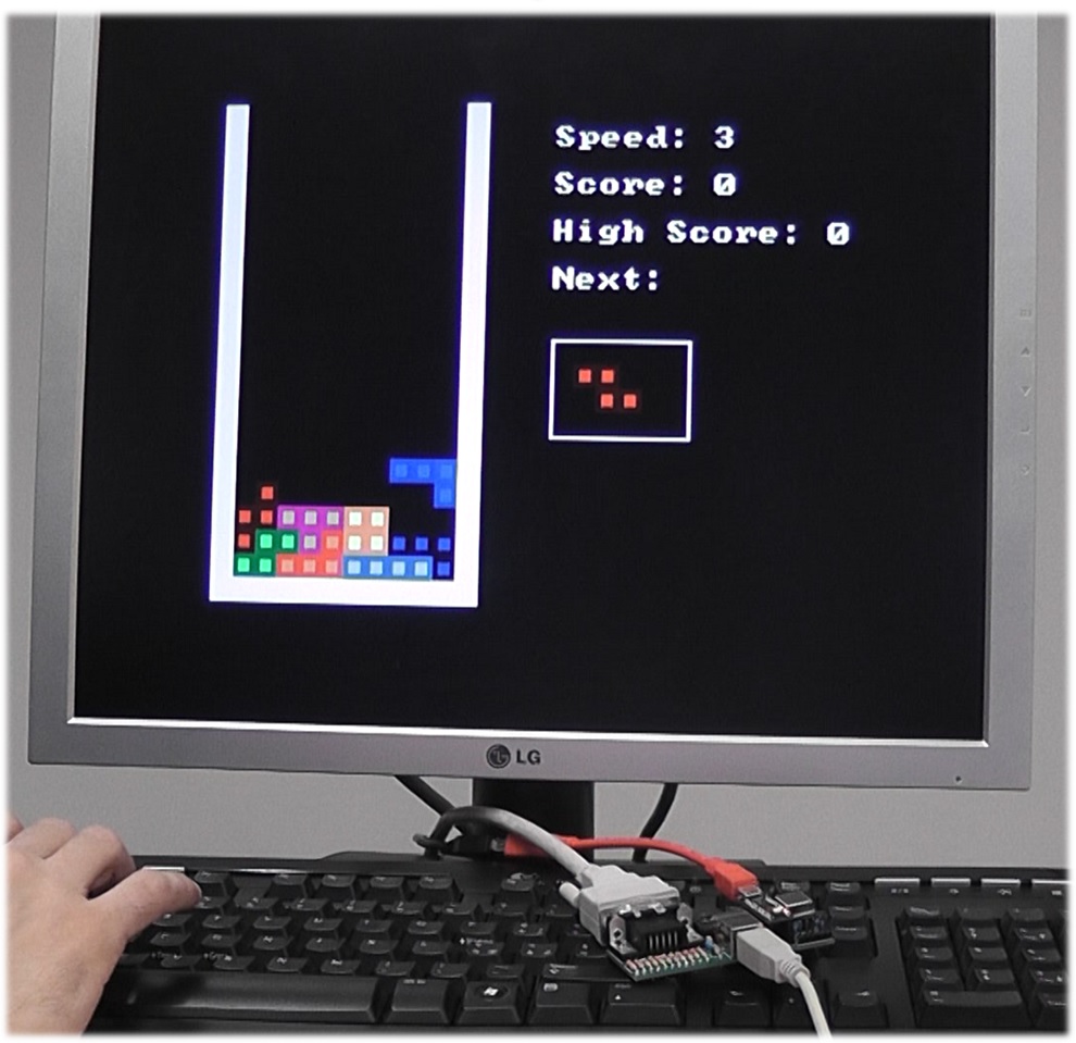
Last year, uChip was presented and, to show its flexibility, several projects with uChip were developed. Among them, there were the hand-held platform game we presented in the post linked here, and a rudimentary VGA console, that ran an even more rudimentary Tetris (see image below).
A light weight USB Host stack enabled using standard USB keyboards. Despite this might still sound complex enough, later we wanted to explore how far we could push the limits of a Cortex M0+. Therefore, we started improving our VGA library, and once progresses were made, we wanted to develop a full featured retro-game console…
The goal
As we wrote in the previous article, the goal of the library was to implement a full retro-game console. In particular we wanted it:
- Easy to build. No fancy (except uChip, which is the heart of uSVC) or tiny SMD parts (except the micro-SD card reader).
- Easy to program.
- Small.
- Low cost.
- And above all: open source.
In the previous part, we briefly introduced the video modes. A console, however, is nothing without:
- Some form of input.
- Storage media to load games.
- Audio.
Input
As previously mentioned before, the input consists of a USB keyboard or gamepad. For this reason, we have heavily modified (well, almost rewritten) an existing USB Host Stack (see credits) so that it works with the VGA, without interfering with the signal generation. We have also developed a lightweight gamepad driver, so that almost all gamepads should be supported. All the USB host functions have been modified to be non-blocking. The USB stack support drivers, i.e. new devices (e.g. mice, USB pen-drives, etc.) could be added.
Storage Media

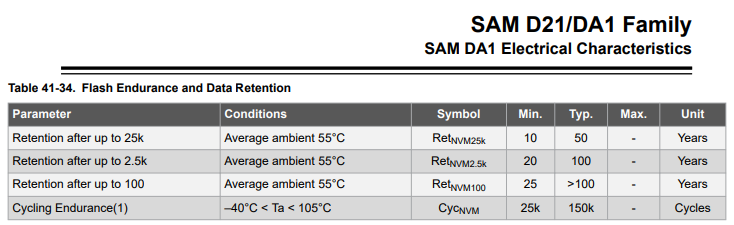
We use an SD card to store the game binaries, which are copied to the internal flash, using the uSVC game loader. Yes, changing repeatedly games will affect the flash reliability. However, from the datasheet, the endurance of the SAMD21’s flash (with more than 10-year retention) is at least 25000 cycles, which is a reasonable value for our purpose.
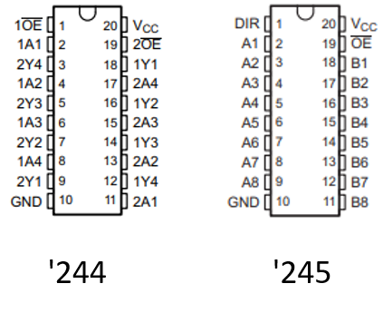
The SD shares some signals with the VGA, therefore, to avoid flickering during SD accesses, we use an external 74AHC245. The 74AHC245 is a bidirectional 8-bit bus driver (aka transceiver), but a 74AHC244 (8-bit unidirectional buffer with tri-state outputs) would have been enough. However, the pinout of the ‘245 is much more PCB friendly, and the price difference with respect to the ‘244 is negligible. The ATSAMD21 microcontroller disables the 74AHC245 outputs (connected to the VGA signals) during SD card accesses (which occur both during the vertical blanks, and in the 80 not used – i.e. black – VGA video lines) so no flickering occurs. When the ‘245 outputs are disabled, they are tied low by the monitor’s 75 Ohm input impedance.
The achieved SD throughput is small (about one sector per vertical blank, i.e. around 28kB/s), and this means that a full 232-kB game takes about 8-9 seconds to load, which is in our opinion acceptable.
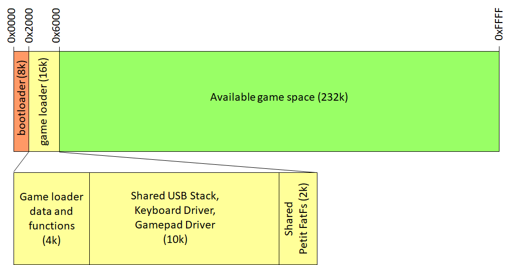
The uSVC game loader sits on top of uChip bootloader, which occupies already 8 kB. This means that 24 kB of flash will be already used, as the uSVC game loader is 16-kB large. The reason of such a large size is due mainly to the USB stack, the two USB drivers (one for the keyboard and one for the gamepad) and to a smaller extent, to the SD card file system library (Chan’s Petit FatFS). Since USB must be used in all the games, and since the SD access functions might be useful too in some, each game does not have to provide the code for USB stack and drivers, as well as SD access, because such code is shared by the game loader. This saves up-to 10-12kB of flash. The initialization functions correctly sets all the pointers and data, so that the functions can be easily called from the game.
Audio

All the video modes support an in-line (i.e. during horizontal blank) 4-channel 30-kSps 8-bit PCM sound mixer, with per-channel 8 bit volume. These are mixed to form a single-channel 10-bit waveform. An optional global first order low pass filter with configurable cut off frequency can be used (the cut off frequency can be modified on each frame).
A reduced single-channel version is used for the bootloader.
Credits where credits is due!
The audio mixer could be driven by any source, but, instead of reinventing the wheel, the UZEBox sound engine by Alec Borque was ported and adapted, with some minor differences.
Instead of 15.7 kSps, the engine runs at 30ksps. Wavetables and PCM are unified (wavetables are just considered as 256-entries PCM samples), therefore there are 4 PCM channels, but the noise generator has been removed. We added also some patch commands, in particular to adjust the sample rate of the PCM samples (which might also have a different sampling frequency than 30 kHz), and change the filter cut off frequency.
We also used other open-source third-party libraries, and these are listed below:
- The default font font8x8.c (and bootfont8x8.c which just removes the first 32 characters to save space on bootloader), Author: Daniel Hepper (https://github.com/dhepper/font8x8/blob/master/font8x8_basic.h).
- Petit FatFS with minor variations to improve code size, Author: ChaN (http://elm-chan.org/)
- Even if the USB stack has been heavily modified (almost completely rewritten and corrected), it was based on the USB Host library for Arduino, Copyright (C) 2011 Circuits At Home, LTD.
- The snprintf function (used in Tetris) of newlib not only is quite heavy, but it required dynamic memory allocation. To prevent this, we used Marco Paland’s printf library (https://github.com/mpaland/printf).
- Dynamic memory allocation is used by rand() and srand() functions too. For the same reason, we used Embedded Artistry’s rand (part of their stdlib library https://github.com/embeddedartistry/libc/).
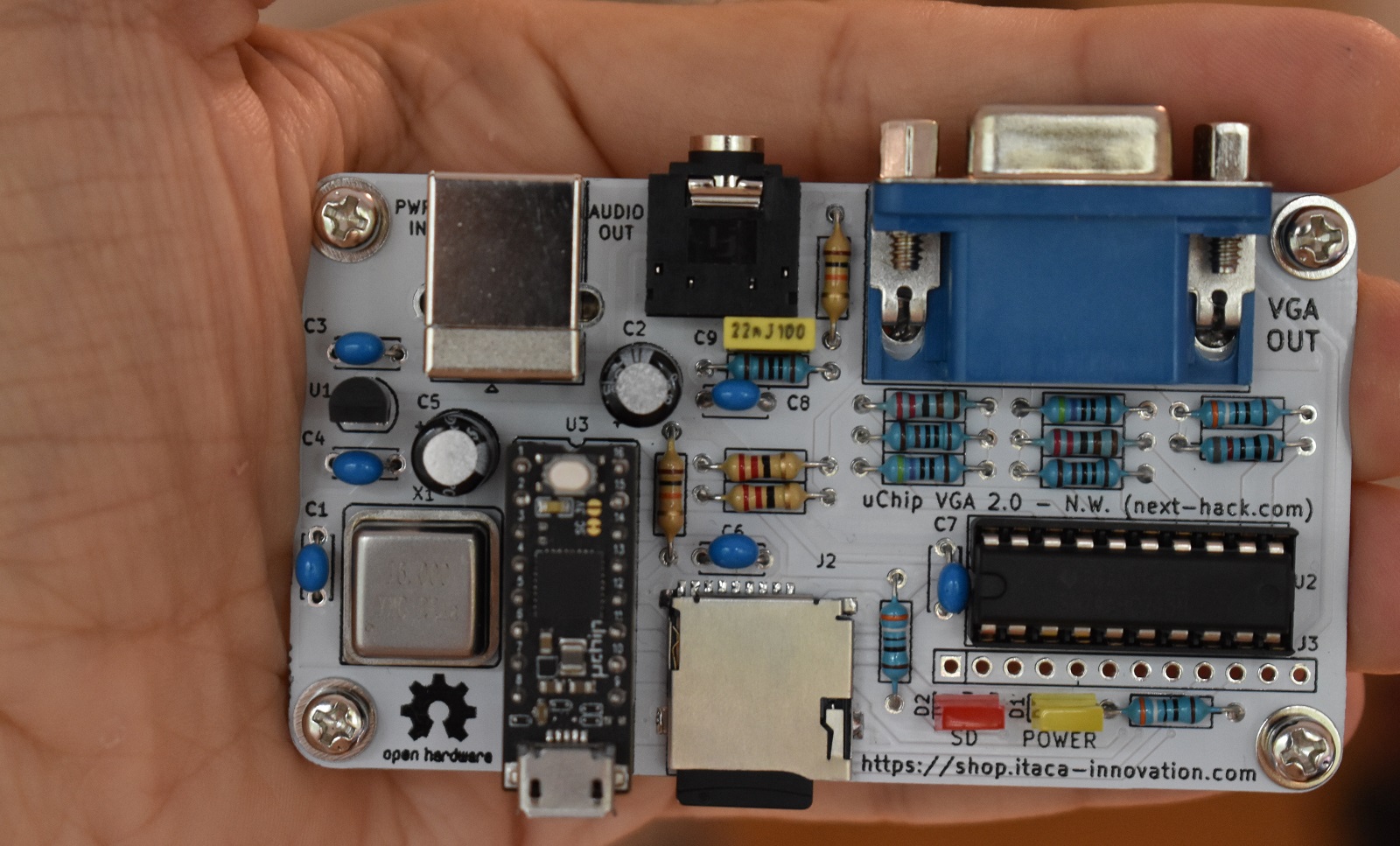
The hardware
The hardware of uSVC is so simple it fits in just only one schematic page! To download the design files, go here!
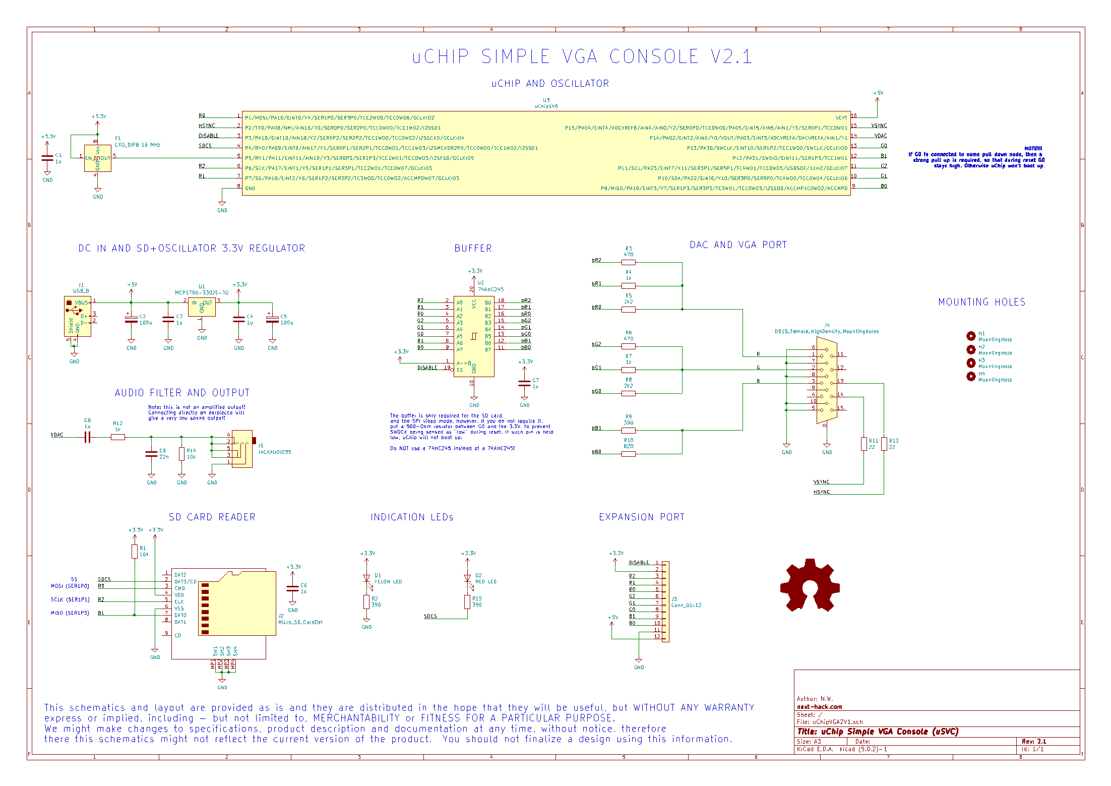
uChip is the heart of uSVC, and is powered by the USB-B connector J1. An external low-dropout regulator (U1) generates the external 3.3V for the SD card and the crystal oscillator. We chose a 16 MHz crystal oscillator frequency, but with minor changes any integer frequency between 1 and 16 MHz will work (this particular frequency was chosen just because of the wider availability when uSVC was designed). The crystal oscillator provides a stable, low jitter reference clock for uChip: stability and low jitter are a major requirement for a stable VGA signal (see previous article).
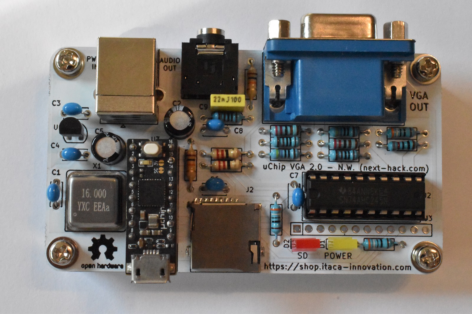
The eight RGB signals coming out from uChip are connected to a 74AHC245 bus transceiver. As said in the previous article, a bidirectional one has been used, because of the more user friendly pinout, since the two buses are located at the opposite rows. On the contrary, in 74AHC244 each input is close to its output.
One might wonder why the “AHC” version has been chosen: speed. If AHC is unavailable, you can safely pick “LVC”, which is even better. By using a cheaper 74HC245 (note: HC, not AHC), one risks of having blurry pixels, because of the very slow rise and fall times of HC devices.
The outputs (actually, the “side” we are using as output) of the 74AHC245 are connected to three resistor based digital-to-analog converters. Instead, the video horizontal and vertical synchronization signals (hsync and vsync) are connected directly to the VGA, using a series termination resistor to improve signal quality.
The output enable of the ‘245 is driven by the uChip, using a dedicated signal DISABLE. It is kept high during SD accesses, so that the ‘245 outputs are at high impedance. During such SD accesses, the VGA signals are kept at 0V (black) by the input resistor of the VGA monitor, therefore no glitches will be visible. The resistor values are calculated so that, when all the signals for one color channel are at 3.3V, the VGA receives a 0.7V.
Finally, the audio is connected to the DAC output of uChip. This is AC coupled to a low-pass filter, to smooth-out the waveform.
The USB input devices, such as gamepads or keyboard, are connected (via an OTG USB micro-A to A adapter) to the USB port of uChip.
The digital signals are externally routed to an optional expansion port, which might be used in the future for instance to add support for other devices such as NES gamepads, Amiga Joysticks, etc.
That’s it, this is all the hardware. Pretty simple, isn’t it?
Download uSVC KiCad design files
The current uSVC KiCad design files can be downloaded from the uSVC github repository.
A 9-bit console?
First, we want to make clear that the term “9-bit” does not come from the actual architecture, which is instead 32 bit.
However, consoles were once classified also by their number of bits: 8 vs 16 vs 32 vs 64, i.e. the number of bits was an indicator of their power and features. For instance, 16 bit consoles had many more colors than their 8-bit counterparts, supported more playfields, bigger sprites, had a faster processor, etc. uSVC surely cannot reach 16-bit console performance like the Super Nintendo or the Sega Genesis, but it is in some parameters superior to the majority of the 8-bit consoles.
In fact, uSVC has a larger resolution and 256 on-screen colors, i.e. many more than the 54 of the Nintendo Entertainment System (NES) and the 64 of the Sega Master System (SMS). It some benchmarks uSVC also outperforms even the NES and SMS.
But we need to talk about this more in detail.
Despite the very fast 32-bit processor, our console is much less powerful even than a 16-bit console. In fact, conventional 8-16 bit console or home computer had dedicated video and sound chips. On uSVC there are no such dedicated chips, and these functions are implemented by software.
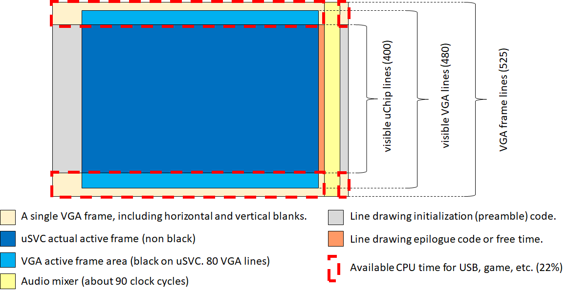
For this reason, even if the Cortex M0+ is a 32-bit microcontroller, most of its computing power is “wasted” to implement the audio and video engines. For instance, there are 525 vertical lines, and during 400 of these, the CPU is busy in generating the video signal, and the audio, which is generated in the horizontal blank. This means that more than 3/4 of its computing power is lost just to output the video signals. Furthermore, when the video signal is not generated, we still need to generate the audio signals, therefore, at the end only 22% of the 48 MHz Cortex M0+ is available for the other tasks. Therefore, it is like if we had only a 10 MHz, instead of 48 MHz, 32-bit processor.
That’s still a very nice computing power, even if compared to some 16-bit console counterparts, or the Amiga 500’s CPU, which had a 7-MHz MC68000 (where even the simplest instructions take at least 4 clock cycles). However, as said before, 8-16 bit console/home computer counterparts had dedicated video and audio chips, and their functions was not just merely generating the video/audio signals, but also they provided graphics capabilities such as block image transfer (the Blitter on the Amiga) and/or hardware sprites, greatly offloading the main CPU. In uSVC, all these functions must implemented in software as well, i.e. using the same CPU.
The DMA is of little help in this case, for a number of reasons, which will be discusses in a future article.
Therefore, of the 10-MHz 32-bit CPU computing power, a big chunk is used to perform video operations, such as drawing sprites and, in general, block image transfer.
So how does uSVC compare to the 8-bit consoles? Let’s take as a reference the SMS, which was the most powerful 8-bit home game machine (according to https://segaretro.org/Sega_Master_System).
A fair comparison is difficult, for several reasons.
First, there are no equivalent video modes between the SMS and uSVC. On one hand, uSVC supports 256 color modes, unavailable on the SMS. On the other, the 4bpp mode of SMS is more versatile than the 4bpp uSVC counterpart, as sprites and tiles have separated 16-color palette, whereas they share the same 16-colors on uSVC.
Second, useful features of uSVC (e.g. sprite flipping, rotation, and automatic size handling) are missing on the SMS, which has instead other useful features (tile flipping, hardware collision detection, sprite scaling), missing, for now, on uSVC.
Third, for uSVC we can only give raw numbers, i.e. calculated by dedicating the full remaining “equivalent 10 MHz processor” power (i.e. after the signal generation has been taken into account) to the single task under test. However, in practice the 10 MHz processor computing power will also be used for the actual game logic, the USB stack and all the graphics operations (sprite drawing, etc.), so the actual figures will be smaller on uSVC. Instead, on the SMS some of these operations (input reading, sprite drawing) could be performed at the same time.
Still, some numbers of uSVC are for sure better than the SMS, and in some cases, not by a small extent. For instance, on uSVC tile copying can be extremely fast, up to 15 MB/s, i.e 2.35-4.7MTiles/s (depending on video mode). This figure is about 800 times higher with respect to the SMS, which could transfer only up to 5616 4bpp tiles per second on a 256×192 screen[1].
uSVC also has some more memory with respect to the SMS[2], and, as said before, it supports 256-color sprites too, unlike SMS. The color change engine also allows for high resolution (i.e 400 lines) color remapping, and the signal drawing routine can perform line remapping and independent x-scroll (all these operations are performed during the scanline, and do not impact on the “remaining” 10 MHz CPU power).
Furthermore, uSVC’s Cortex M0+ provides single-cycle 32×32 bit multiplications (as well as other 32-bt arithmetic and logic operations), therefore, on cycle by cycle basis, uSVC has a much more powerful CPU with respect to SMS.
The main aspect in which SMS is somewhat superior with respect to uSVC could be the sprites. In fact, from our demos we verified that uSVC is able to handle more than 64 on-screen 256-color 8×8 sprites, but the SMS supports up to 64 16-color 8×16 sprites (twice the size, but half the bits per pixel).
However, when dealing with big sprites (32×32), uSVC can show up to nine 256-color sprites. On the SMS you must use eight 8×16 sprites to create a 32×32 sprite, and this means that at most you can show only 8 of these “bigger” sprites. Still, some tricks allow to show more than 64 sprites per screen on the SMS.
Noticeably, if there are sprites smaller than 8×8, uSVC can take advantage of this, and show more than 64 sprites. Furthermore, if sprites are tile-aligned (i.e. on a 8×8 grid), uSVC can show more than 128 256-color sprites.
So, in terms of ’80’s and ’90’s standards, uSVC would neither be 16 bit, nor 8 bit. 9 bit!
To be continued…
Of course the story continues! We are working to publish soon the editor, the kernel, and the guides with some examples, to let you get some confidence with uSVC!
[1] From https://segaretro.org/Sega_Master_System/Hardware_comparison.
[2] Even if about 3kB are used for the drawing routine, which is stored in RAM. However, sprites do not have to be stored in RAM.