
NOTE!!! This is the fourth part of the tutorial “How to play a 20 fps video on Arduino”. If you haven’t read the previous steps, you might find them in the links below:
- Part One (introduction)
- Part Two (hacking the module to achieve high speed transfer on the SD)
- Part Three (SPI v.s. USART in SPI mode)
WARNING: the correct download link of the sketch is this one. The old one is missing a “static” keyword, so it does not compile with Arduino 1.18 and later!
Introduction
Hi there!
Welcome to this part, where we will finally play a 20 fps video on a 160×128 pixel display, with 65536 (16 bits) colors! We will also show you what was inside of the magic box!!!
As we said in the previous posts, the computing power of the Arduino Uno and its memory capacity are very limited. Therefore even playing a 20-fps video with 65536 colors in 160×128 pixel is not an easy task.
We used the module shown below.
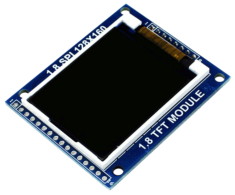
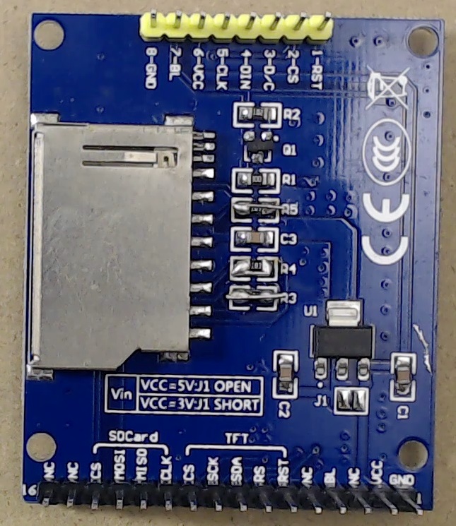
Fig. 1. This is the MODIFIED version of the display module. R3, R4, and R5 have been shorted to enable 8-MHz SD transfers!
That module has built in the SD card, however, you must hack it to be able to use the full 8MHz clock speed. We already spent an episode in hacking such module (link here). This step is mandatory if you are going to use this exact model!
Of course you can use separate Display and SD boards, provided that the display has compatible controller (ILI9163) and that the SD board can actually sustain 8MHz. Some other controllers, such as ST7735R, might work too.
The two main ideas behind this project
When dealing with videos, one must find a tradeoff in terms of computing power and file size or bandwidth, depending on which is the most limiting/costly factor. The Arduino Uno has no computing power at all to perform even the simplest on-the-fly decoding, such as the RLE (run-length encoding), which would be also totally useless in many cases.
On the other hand, one of the main ideas behind this tutorial is that the price of SD cards is very low, and cheap 4GB or larger cards can be bought for few bucks. Thus, the whole video can be stored in a raw format, which can be directly fed to the display. This will free us from the need of any data processing, a job that our Arduino is not capable of, even in its simplest form. Our display has 20480 pixels, which therefore require 40960 bytes for each frame (16 bits per pixel). This means 819.2 kB (800 kiB) per each second of video. This might seem huge (and in fact it is!), but a cheap 4GB card can store 5000 seconds (about one hour and 20 minutes) of video. Remember that in the past post (link here) we actually managed to get only 627kB/s. However, we achieved such a small throughput because we were reading only one sector per read request. A much better performance can be achieved with larger read requests.
Even if storing the video in the raw format solves the problem of the real-time decoding, we must face another problem. The bandwidth.
In fact, let’s consider the following circuitry, in which the SPI (either the SPI or the USART in SPI mode) is shared between the display and the SD. This would require a bandwidth of 1600kiB, because we would need first to read the data, then send it to the display. This means that the SPI clock should be at least 13MHz (assuming no overheads), which is not possible on the ATMEGA328P.
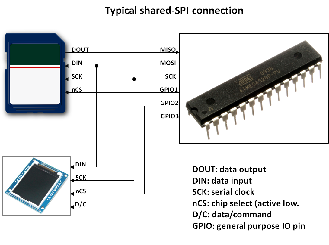
Fig. 2. This is a typical SPI bus implementation. All the peripherals share the same MISO, MOSI and SCK lines.
Another way would be to connect the SPI to the display and the SD to the USART, and quickly send the data to the SPI as soon as we read it from the USART (or vice versa). However, we already found that with the SPI it’s very difficult to get even close to 800kiB/s, so we must exclude this idea.
Considering the shared SPI bus (in our case implemented with the USART in SPI mode), if we do not need any data processing, we actually do not need to transfer the image data from the SD card to the microcontroller and THEN from the microcontroller to the display. Instead, we can use a technique that resembles the direct memory access, as known as DMA (even though this is a direct peripheral to peripheral transfer). This is the second main idea behind this project!
For this purpose, we can connect the display data input to the SD card data output. In this way, when we ask the SD Card to output the image data, the display will be able to read it, without CPU intervention. The CPU only has to enable the display at the correct time, which is a trivial task (and of course, the CPU must send a 0xFF value to the USART, to initiate the read operation of the next byte).
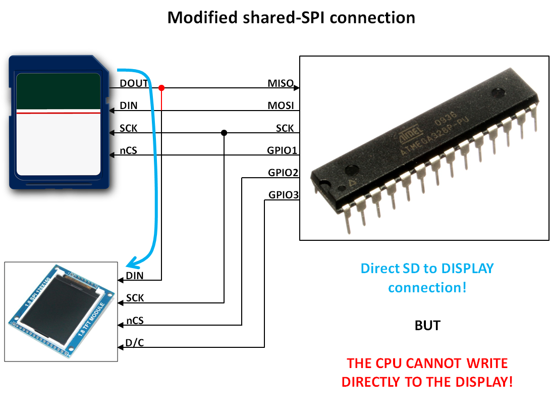
Fig. 3. This is the modified shared-SPI connection: the display’s DIN line is not connected to the MOSI. Instead (see the red wire, indicating the difference between against the previous figure), it is connected to the SD’s DOUT line.
However, the simple direct connection shown in the previous figure has a major drawback: the CPU cannot drive directly the display. In this way:
- We can’t easily configure the display. A workaround for this is to store in the raw file not only the video data, but also the configuration commands too.
- We can’t draw anything to the display: we can’t draw texts, lines, etc. Everything should be preloaded in the SD card. For this particular project, in which we just play a video, this would not be a problem. However, in most of the other project this would be a very hard limitation.
A straightforward solution is to selectively connect the display data input signal to the MOSI or MISO signals, using a multiplexer. By using an additional general purpose I/O pin (GPIO) we can then instruct the multiplexer which signal we would like to connect to, as shown in the figure below.
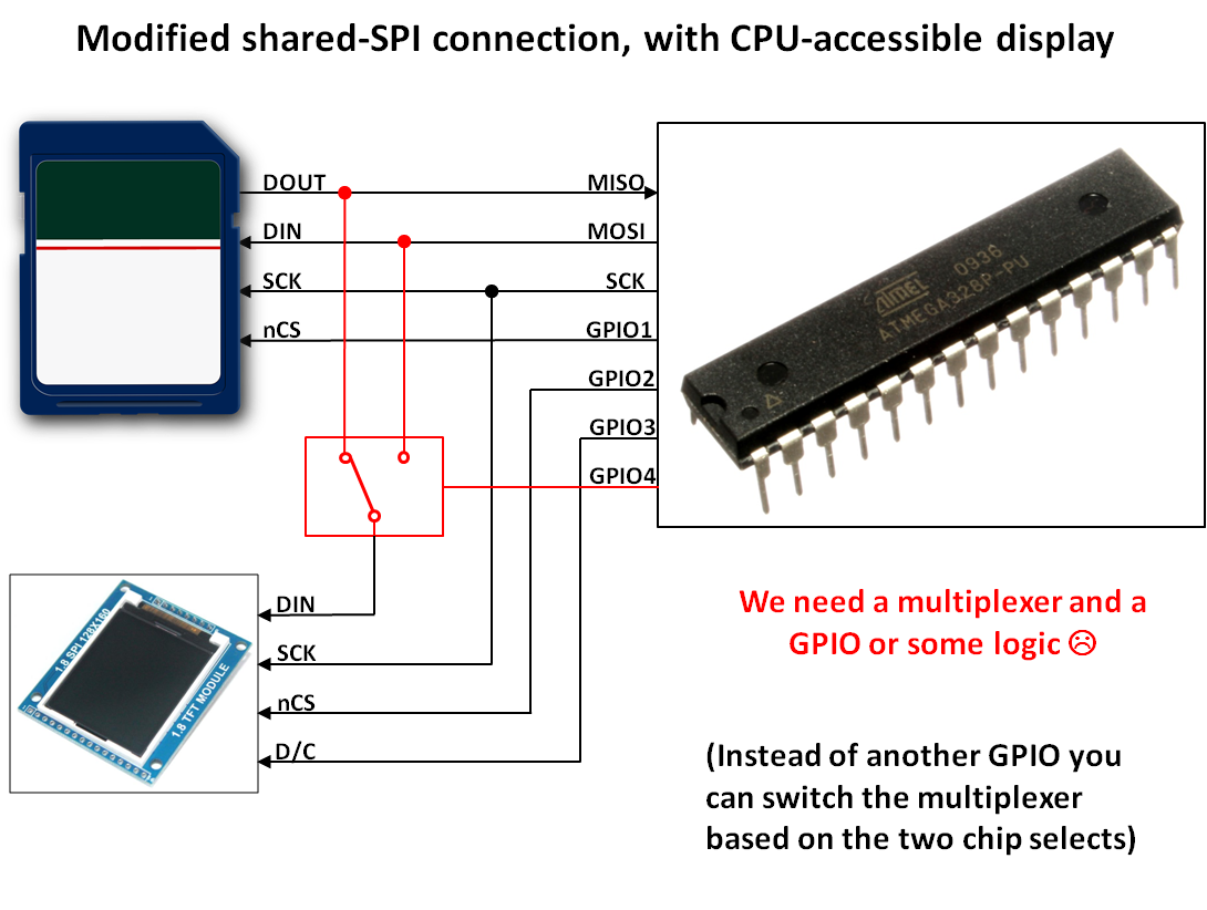
Fig. 4. Adding a multiplexer solves all the problems of the previous figure!
But, hey… an additional signal? An additional multiplexer IC? This is not really optimized! That’s not for us! We are in next-hack, after all, isn’t it 🙂 ?
A much smarter solution is… a simple resistor!
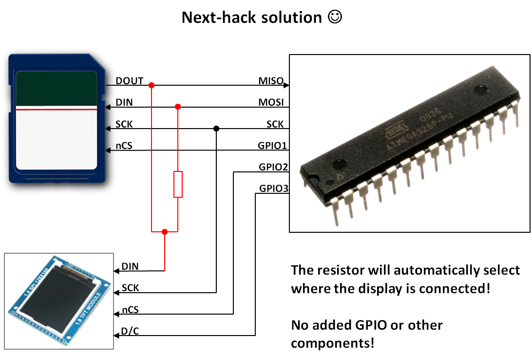
Fig. 5. Next-hack solution! A single resistor solves all the problems 🙂
In fact, we can connect the display directly to the SD card data output (MISO signal) and connect also MISO and MOSI through a resistor. In this way, when the SD card is not selected, its data output is in high impedance, i.e. is disconnected, and our microcontroller (MCU hereafter) can still send data to the display, through the resistor. If the SD card is selected, then we have a direct connection between the display and the SD card! Perfect!
To better clarify, here are the 3 possible configurations. The light-blue lines indicate the signal path.
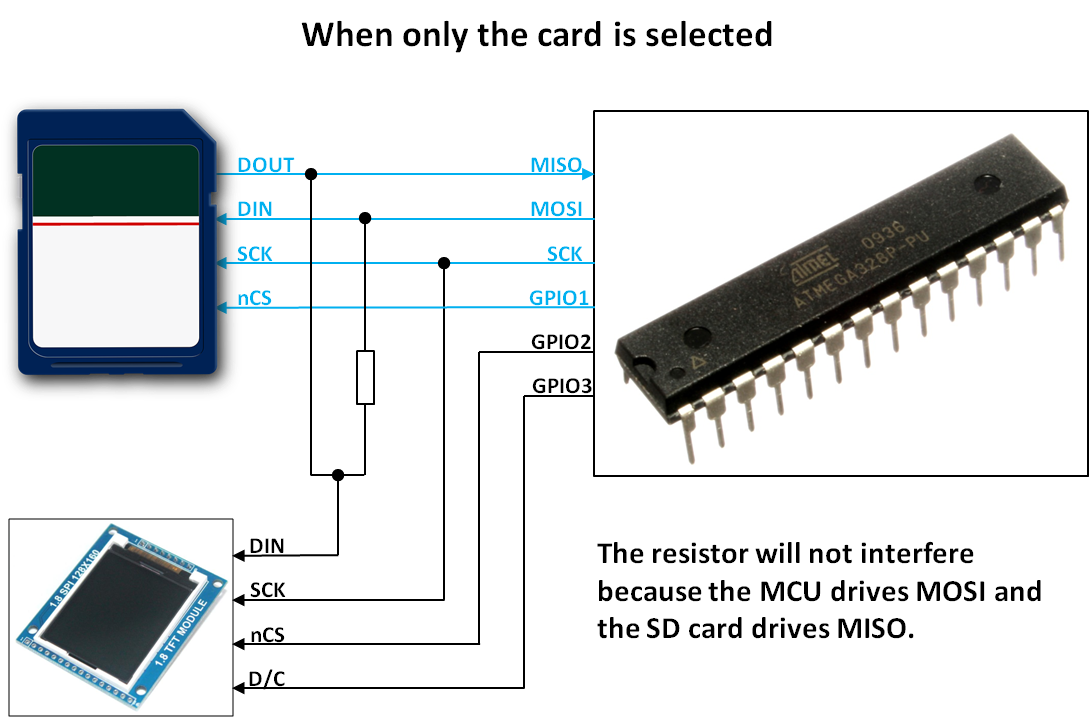
Fig. 6. When only the card is selected, the system is a standard SPI bus. The resistor will act as a load, but if its value is large enough, it will not interfere with the logic levels.
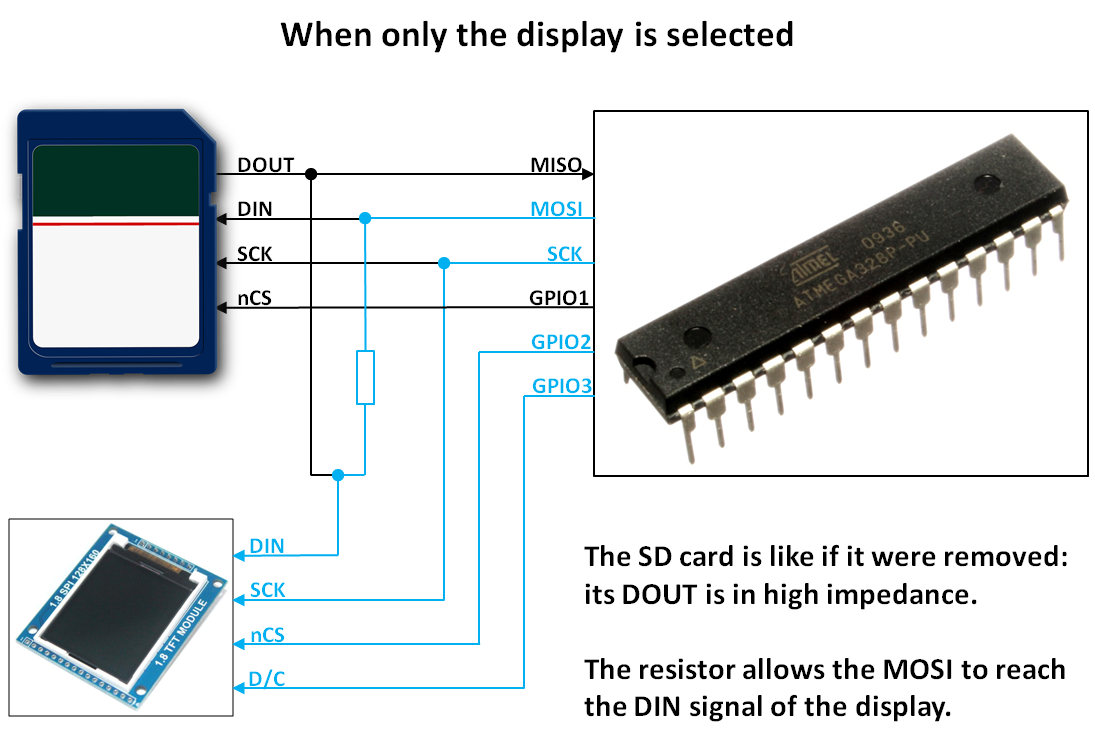
Fig. 7. When only the display is selected, the SD is actually disconnected from the SPI bus and it does not interfere. The signal passes through the resistor to the display. The resistor value must be small enough to enable 8MHz transfers.
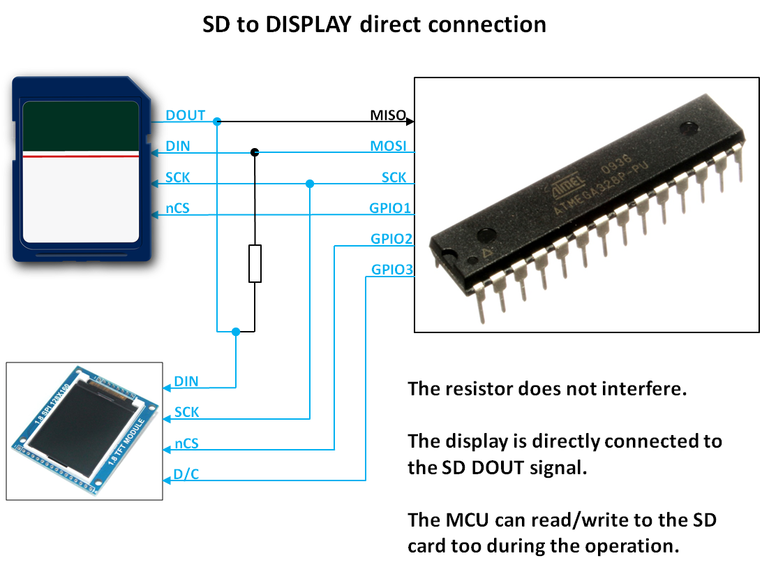
Fig. 8. Direct SD to display transfer! The CPU is directly connected to the SD card, and continuously sends 0xFF to the SD. The data outputted by the SD is directly seen by the display! The resistor will merely act as a pull-up (the MOSI line is high, as we are sending 0xFF). However, its value will be large enough, therefore we won’t have any trouble.
All we have to do is to make sure that the display is not selected when we send control data to the SD card, and to select the display when the SD card is outputting the display data! Sound simple, isn’t it?
In practice, you’ll need to carefully select the resistor value. We found that in a 3.3V system (e.g. uChip, Arduino Due, Arduino Zero, etc), a simple 1-kOhm resistor is enough to complete our entire video playback system! Yes, you need just one 1k-Ohm resistor on a 3.3V system, that’s it!
However, remember that you’re connecting the display to a 5V system, so each signal must be converted from 5V to 3.3 V. We saw in the second episode, that a pair of 1.5k and 1k Ohm resistors is adequate for such a task. However, when you’re also making the connection between MISO and MOSI, you’ll need to change the values, to make sure that in each condition the display and the SD card receive good signals levels (i.e. with the appropriate voltages according to the logic levels).
We now show some considerations on the calculation of the resistor values. The final values are shown in the schematics below!
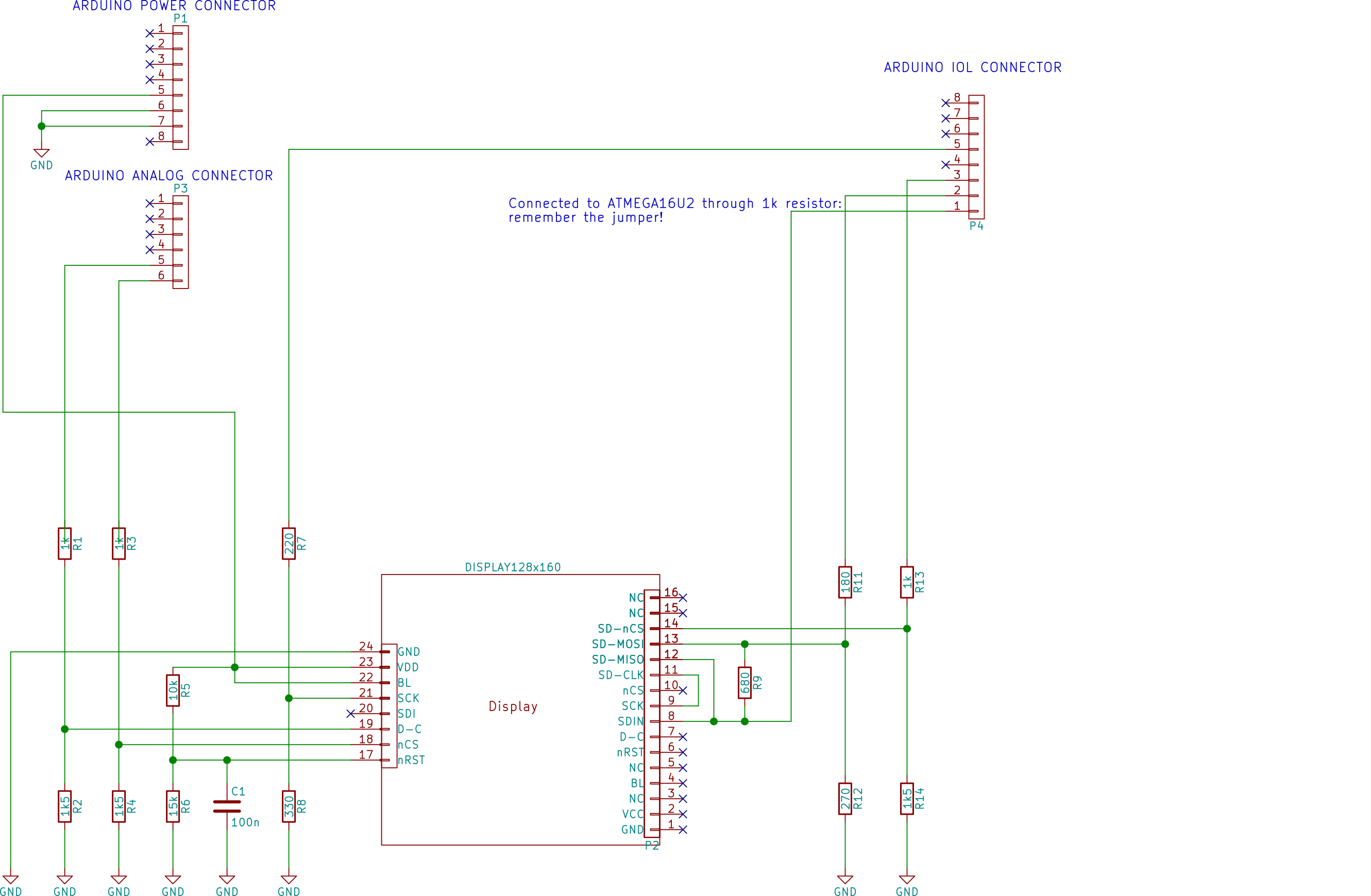
Fig. 9. The final schematics, with the resistor values! Please note that the display lines (SCK, SDI, D-C, nCS, nRST) are connected to both the connector on the right and on the left. We used the connector either on the left or on the right, to facilitate and simplify the layout.
Calculating the resistor values
The most critical part is made of R9, R11, and R12. In each of the three cases, shown in Figs 6-8, these resistor must grant enough bandwidth and meet the high and low voltage level constraints.
In the following, we indicate with the “//” symbol, the parallel of the two resistors. For instance, R1//R2 means R1*R2/(R1+R2).
During direct CPU to DISPLAY command:
– When the CPU only selects the display, the display is connected to the CPU through R9 and the resistor divider formed by R11 and R12. The total resistance is R9 + R11//R12 and, due to speed constraints, we would like it to be strictly less than 1k Ohm. This limiting value was found when hacking the display module.
During CPU to SD command
This is the trickiest part. The CPU outputs a value, but the SD is also answering on its SD-MISO signal, which is connected to the SD-MOSI, through R9. Since we have two values of desired MOSI and two possible values of MISO, we need to make sure that, in each case, the voltages at the SD-MOSI signal are within the right range.
In particular, such value is determined by the following equation:
![]()
Here is a table, with the four cases, with the used resistor values. Each cell indicates the voltage seen by the SD DIN input line (SD-MOSI), with the corresponding CPU MOSI and SD MISO value.
| CPU MOSI VALUE | |||
| LOW (0V) | HIGH (5V) | ||
| SD MISO VALUE | LOW (0V) | 0 | 2.59 V |
| HIGH (3.3V) | 0.45 V | 3.04 V | |
These values are all acceptable, but they are too optimistic, because when the SD and the CPU output opposite polarities, the voltage at their output will be somewhat different, because of the non-zero output resistance of their buffers. The SD card’s MISO output voltage could depend on the particular card used. However, for our calculation we can take the worst-case scenario, in which the SD card has a zero Ohm buffer, i.e. VOH = 3.3V and VOL = 0V. The voltages at the CPU’s pin can instead be taken from the ATMEGA328P datasheet. Assuming a linear dependence on the output voltage variation (relative to the rail), we achieve a VOH =4.4V and VOL = 0.2V. With these values we achieve:
Worst case low voltage MOSI at SD: 0.56V
Worst case high-voltage MOSI at SD: 2.57V
These values are both within the SD accepted range.
During SD to CPU or SD to DISPLAY
Here the problem is that the SD output is loaded by the 680 Ohm resistor. Furthermore, the SD is powered at 3.3V while the ATMEGA328 is powered at 5V. Luckily, when reading from the SD card, the CPU MOSI is high, and this, due to the divider induced by R11 and R12, has no effect to the high-level output voltage, which will be 3.3V, i.e. 0.3 V more than the worst case condition. (still in the ATMEGA328P datasheet the typical voltage above which the pin is detected as high is 2.5V). Problems might arise when the SD output is low, however, the maximum VIL is 1.5V when the ATMEGA328 is powered at 5V. Furthermore, the datasheet shows that the pin is detected as low if its voltage is below 2V.
Clock resistor divider
To tweak the setup/hold times, we also used a resistor divider with a total resistance lower than the 1.5k/1k pairs we used in the first episode. In fact, we used 330 and 220 Ohm, which grant us a 5-fold reduction in terms of propagation times between the CPU clock and the SD/display. This is crucial while reading, as a delayed clock would mean a delayed readout.
Well, enough talking! Let’s go for the next hack!
Hardware/software requirements
In this hack you will require the following hardware:
- An Arduino Uno or compatible. Alternatively, you can use any MCU (microcontroller) of your choice. We haven’t tested this on PICs yet, but they might work as well.
- A bunch of resistors (see schematics for the actual values).
- Some wires.
- A jumper required to keep the ATMEGA16U2 in the reset state while the video is playing. This is mandatory!
- The Display + SD card reader board. You can also use two separate boards: one for the SD, one for the display. Note: if you use the same display we have shown you, be sure to hack it how we did in the second episode.
- A breadboard or a prototyping board (and a soldering iron). We preferred using a prototyping board, because it yields a cleaner layout, but if you’re courageous, you can use a breadboard too.
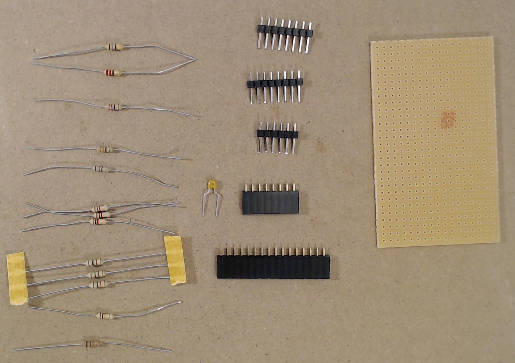
Fig. 10. The components required for creating the shield for the Arduino.
Here is the software required:
- Any IDE of your choice. Arduino IDE is “fine”, but you can also use Atmel Studio too, or another IDE of your choice. Let’s be sincere! The Arduino IDE is one of the worst IDE in the world and we don’t like it. It is severely limited, yet it is quite slow too. Not to mention when compiling… Still, many people use it, especially those at their first experiences with MCUs. So, we made an effort and used it!
- ffmpeg to convert your video in a sequence of bitmaps. Link to its download page here.
- Our bmp2rawVideo utility that joins the BMP images into a single raw file. Here you’ll find the source code, as well as the precompiled executable (in the folder bin/Release).
The full Arduino source code of this project is available here.
Let’s go for our next hack!
Step One: preparing the hardware.
Note: Hack your SPI display+SD module as we did in the second episode. This is mandatory to get 8MHz if you’re using the same display!
Next prepare the circuit as shown in the schematics shown previously.
We strongly suggest you to use a prototyping. Here is the suggested positions of components (the green tracks are in the BOTTOM side).
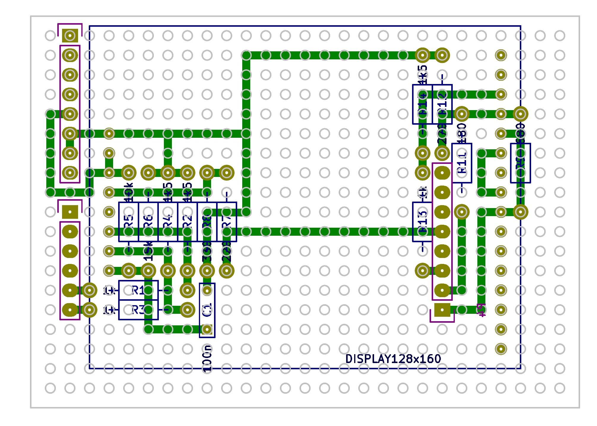
Fig. 11. Layout (seen from the TOP side!) of our shield. Green tracks are at the bottom side!
Here you can see our results:
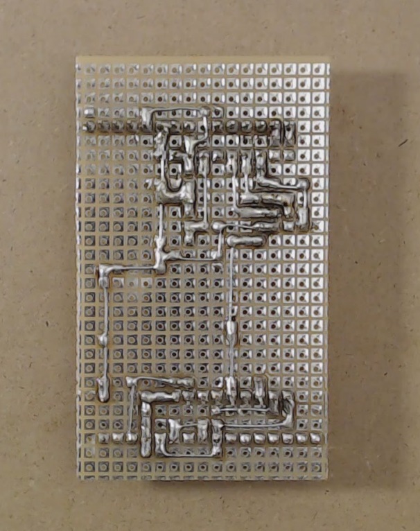
Fig. 12. Bottom side of the shield.
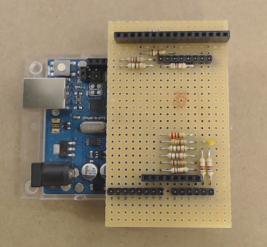
Fig. 13. Finished shield, mounted on the arduino.
Note: we also modified the headers so that we can easily solder them on a one-sided board. All we need to do is to press the plastic part on a flat rigid surface using pliers (see below) until all the terminals are at the same level with the plastic.
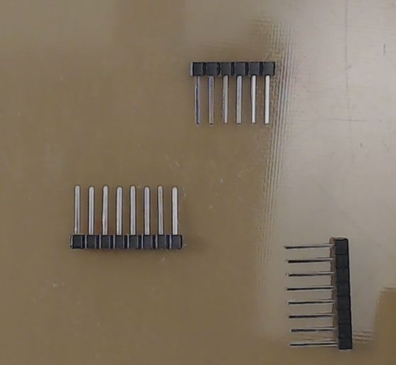
Fig. 14. Modified headers, to be mounted to the shield. This allows using a single-sided board. This was achieved pressing the header onto a hard surface (a blank pcb), using a plier.
Step Two: Creating the Firmware
Download the sketch with the modified FATfs library. This time we added a modified version of the f_read() function, which reads the desired amount of bytes. For this purpose, in ff.c we copied and renamed f_read() to f_mmc_to_display_direct_transfer(), where we select both the display and the SD card. The function f_read() called another function, disk_read()that is located in diskio.c. That function calls mmc_disk_read()in mmc_avr_usart_spi.c. Therefore, we copied mmc_disk_read() and renamed to mmc_to_display_direct_transfer(). Of course, now f_mmc_to_display_direct_transfer() calls mmc_to_display_direct_transfer(), instead of disk_read(). In mmc_disk_read(), another function was called: rcvr_datablock(). This was copied and renamed to datablock_to_display_direct(), which will be called by mmc_to_display_direct_transfer(). In rcvr_datablock(), the function rcvr_spi_multi() was called. Finally, this is the function we were looking for! We copied and renamed it to spi_multi_mmc_to_display_transfer(). This is the function (instead of rcvr_spi_multi()) that datablock_to_display_direct() will call. There, we make sure that the display is selected when reading the block, and deselected when the block has been sent out. Contrarily to the original version of the functions, we do not need any read buffer, as the data is directly transferred to the display.
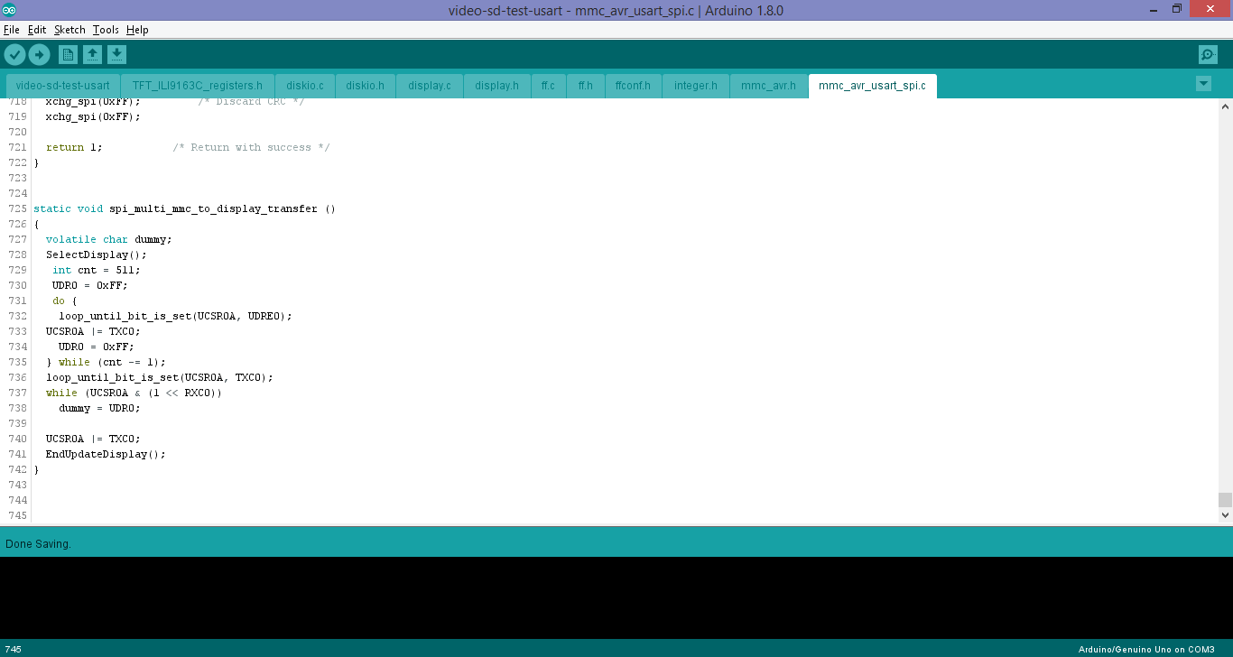
Fig. 15. The final function, which actually selects the display before the sector is read, and deselects it after the sector has been read.
The rest of the program is very simple:
- Prepare the SD card and open the file “video.raw”.
- Loop:
read an entire frame. - Optionally: synchronize to 20 Hz (uncomment the line
synchronizeTo20Hz();in the source) .
Step Three: converting the video
Conventional video cannot be used. We need ffmpeg to save frame-by-frame our original video. With ffmpeg we can also perform the following tasks, at once, which are mandatory:
- Convert the video to 20 fps.
- Convert the video resolution to 160 x 128 pixels.
You can also use your favorite tool to export your video to 24-bit bitmaps frames with a resolution of 160×128, at 20 fps. The choice is yours!
The command line parameters needed by ffmpeg are:
ffmpeg.exe -i <input video> -r 20.0 -vf "crop=in_h*160/128:in_h,scale=-2:128"
"<output directory>\frame%4d.bmp"
Where, <input video> is the original video you want to convert, whereas <output directory> is the directory where you want to store the images, with the file name frameNNNN.bmp (NNNN is a 4-digit number from 1 to last frame). The %4d indicates ffmpeg that it should save the frames with a progressive 4-digit number. On longer videos, 4 digits are not enough. Therefore you should write 5 (which is enough for 5000-second video. For even longer videos, use 6!).
For instane, to convert the video video.mp4 in D:\Video\video.mp4, and save it as a collection of frames in D:\Video\Frames\, you must write:
ffmpeg.exe -i "D:\Video\video.mp4" -r 20.0 -vf "crop=in_h*160/128:in_h,scale=-2:128"
 "D:\Video\Frames\frame%4d.bmp"
So open the command line (Windows-r and type cmd.exe) and write to the prompt the line above (With correct parameters). After you press enter you’ll end up with something like:
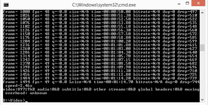
Fig. 16. Output we got after converting the video of next-hack youtube channel presentation.
Then use our command line tool to convert the 24-bit bitmaps to a single big raw file.
The command line string must be:
bmp2raw.exe -i <input_file> -o <output_file>
where:
<input_file> must be in the form:
“directory\base_file_name%04d.bmp”. If you converted your video using 4 digits.
“directory\base_file_name%05d.bmp”. If you converted your video using 5 digits.
“directory\base_file_name%06d.bmp”. If you converted your video using 6 digits.
<output_file> must be the full path to video.raw (e.g. D:\video.raw)
Following the previous example, to convert the frames created with ffmpeg, write:
bmp2raw.exe -i "D:\Video\Frames\frame%04d.bmp" -o "D:\Video\BigFile\video.raw"
Note! The previous example assumes that the directory D:\Video\BigFile exists!
After you’ve created your big file, you should end up with something like the figure below.
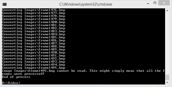
Fig. 17. Output when converting the frames to a single big file.
After that, copy video.raw in your SD card! We recommend you using SD cards formatted using cluster sizes of at least 16kB! As explained in the previous episode on youtube, large cluster size allow for better performances.
The source code of our command line tool (So that you can compile it also on linux or mac) is here.
Step four: program the MCU
- Program the arduino with the sketch we provided.
- Remove the power (i.e. the USB cable) to the Arduino.
- Insert the jumper as show in the figure below. REMEMBER TO REMOVE THE JUMPER AND THE SHIELD WHEN PROGRAMMING, AND PUT IT BACK WHEN USING THE SHIELD
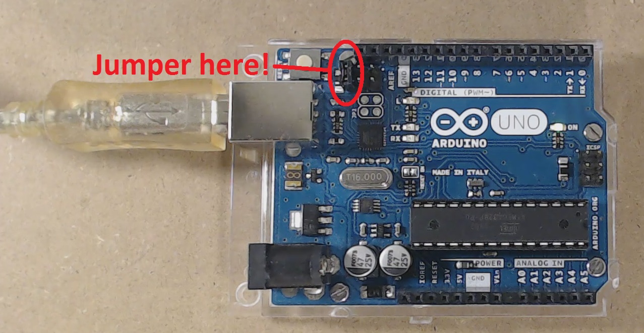
Fig. 18. Be sure to put the jumper in the shown position when you want to play the video. Remove the jumper when you want to program your Arduino! Remove the power when inserting/removing the jumper and/or the shield!
- plug the shield with the sd card inserted.
- Connect the USB/power cable to the Arduino.
Step Five: Enjoy!
There is nothing more to do, except enjoying how much you have squeezed out of few minutes of work! The video should start in few seconds.
Performance
Performance depends on the SD card access time (different cards have different access time values), and on the cluster size: the larger the cluster size, the better are the performances, because it means longer chains of consecutive sectors, therefore we need fewer reads of the FAT table. We suggest cluster sizes equal to or larger than 16kB (use FAT16 whenever possible).
As you see, we are reading in very large chunks, so that we can amortize the relatively long time required for the SD to output data. Also we amortize the software overhead and also with only one command we as the SD to output more than one sector. This will allow us to get very close to the theoretical limit.
To measure the frame rate, you have two choices:
- measure, with a frequency meter, the display nCS pin, which will toggle with a frequency. Such frequency is 80 times the actual framerate. This is because each frame has 80 sectors, and during each sector read we keep the display chip select low, while keeping the high after the readout is completed.
- Alternatively, you can also measure, with a scope, pin C0, i.e. the analog 0 port. Such pin will have a frequency which is half of the actual frame rate (in fact, the pin is toggled each frame, using the instruction:
PINC = 1;).
Here’s what we achieved. What did you achieve? Put a comment below!
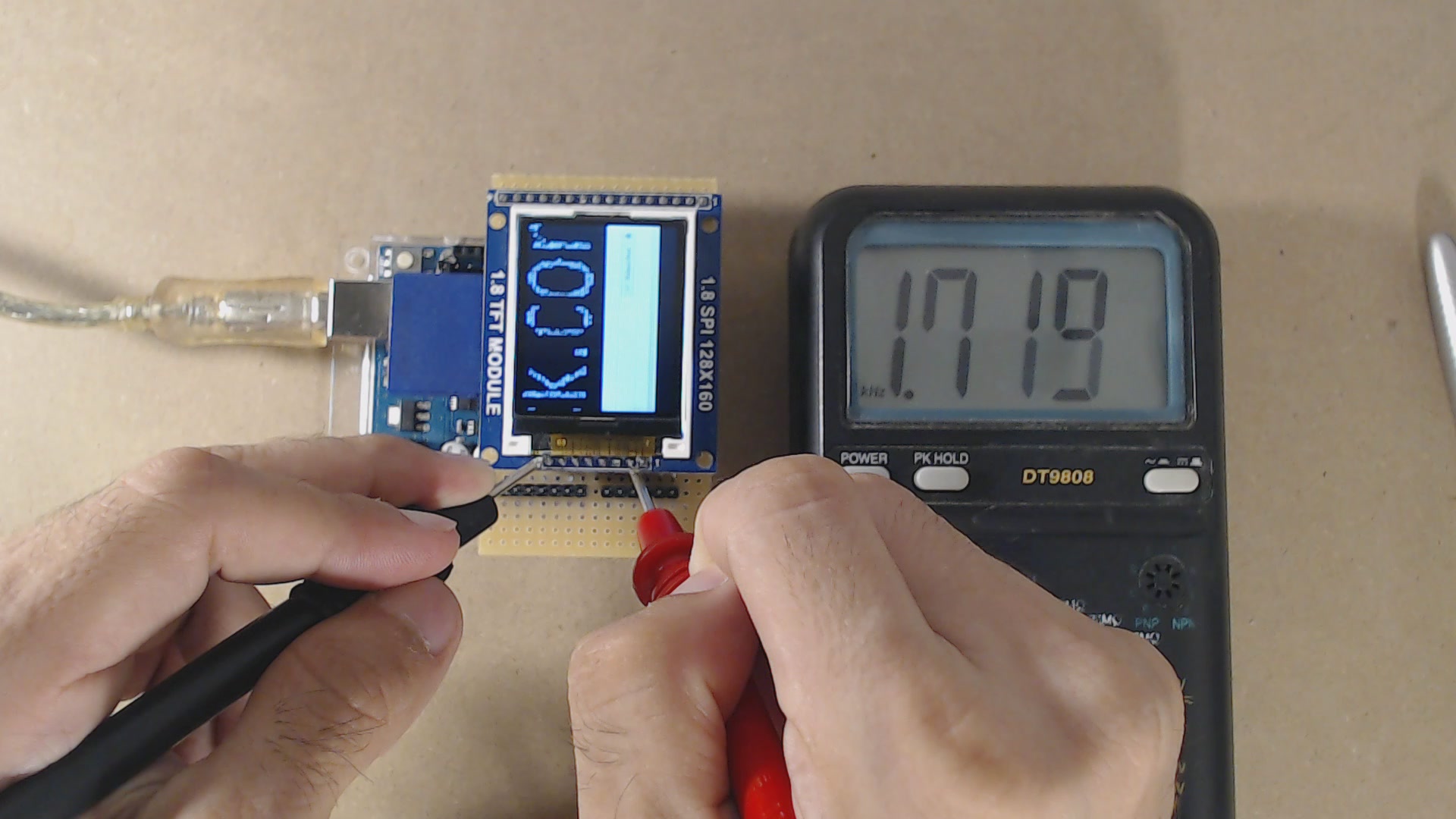
Fig. 19. Measuring the frame rate on the nCS pin (which has a frequency 80 times the actual frame rate).
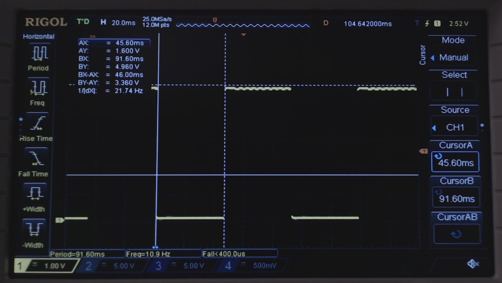
Fig. 20. Measuring the frame rate from the pin C1 (analog pin 0) with a scope.
As shown in the video, the frequency is not stable, but it’s always larger than 1712 Hz. This corresponds to a minimum frame rate of 21.4 fps. This means 875 kB/s which is extremely close to the absolute maximum theoretical value of 1000kB/s !!!
If you want to achieve exactly 20 Hz, uncomment the line synchronizeTo20Hz(); If that line is uncommented, you’ll get results similar to those we reported below:
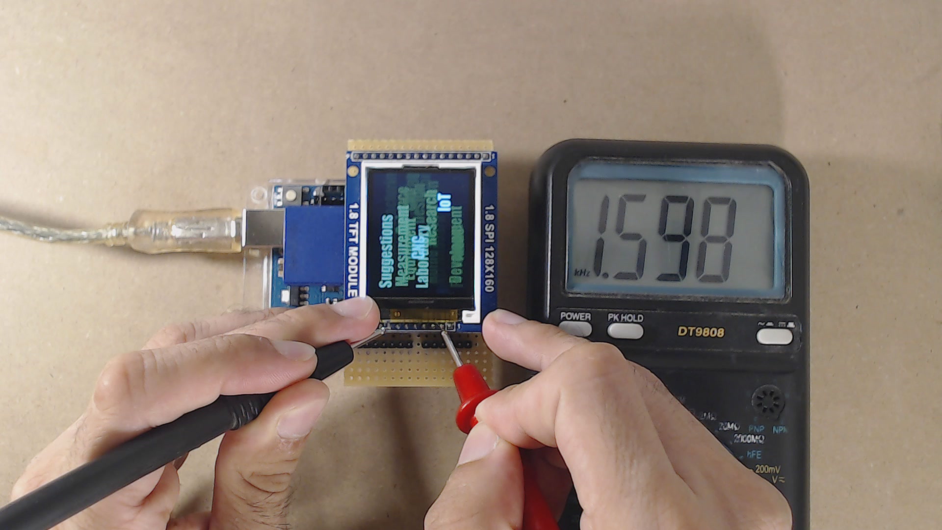
Fig. 21. Measuring the frame rate on the nCS pin, when the synchronizeTo20Hz() function is called. The nCS frequency is about 1600 Hz, i.e. the video is running at 20 fps.
Fig. 22. Measuring the frame rate from the pin C1 (analog pin 0) with a scope.
As a last remark, let us spend some words on the code without synchronization. This is an useful tool to assess how much headroom we have left for the audio. We got a minimum frame rate of 21.4 fps. This means that we have a bandwidth equivalent to 1.4 fps, which is available for the audio. 1.4 fps means about 57kB/s. This is enough for a 20kHz, 16 bit audio, which requires 40kB/s! However, this value shows also that our headroom is not so large, therefore we will have to optimize our code, to get a full 20fps video with 20 kHz audio @ 16 bit!
The magic box
Hey! Wait! You promised us to show where is the magic box! We see no magic box!
Look closer, it’s below your very eyes! It’s the 680-Ohm resistor! It automatically performs the peripheral to peripheral direct transfer (ok, the CPU provides the clock!) and it allows also the CPU to talk directly to the SD or to the Display. 3 things in a single passive component!
Thanks to this little guy we just cut in half the required system bandwidth!
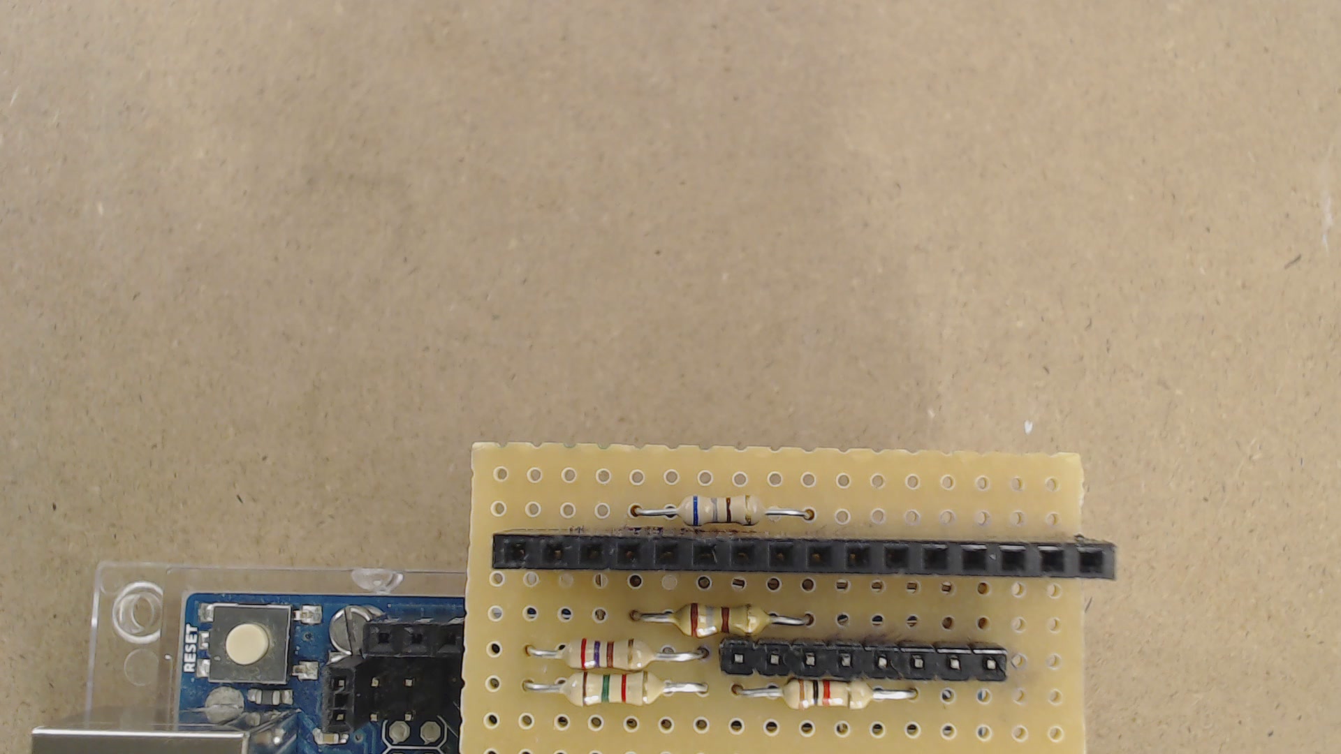
Fig. 23. The magic box is that 680 Ohm resistor, which connects the SD output line to the display input line!
That’s all for today! Do not miss the next post, in which we will show how to play a 16-bit 20 ksps audio file! This will be needed for the last step, the integration of audio and video. For a video guide, check our youtube channel!
Otherwise, you can watch it here!
Hi there, I was just wondering when you will be releasing video 5/6 decoding the audio for this project?
Hi Ian, sorry for the delay. We had been developing another project, and we also moved our lab in another country 🙂
Part 5 will be ready soon, both as video on youtube and here!
Hi again!
The article is ready now! Unfortunately the video will be available later!
Thank you very much for this tutorial
Dear next hack
Nice to meet you.
Thank you for publishing a wonderful project.
I am in trouble with raw file creation.
I made many bmp files with ffmpeg.
I tried to create a raw file with only movies from many bmp files.
I typed the following command through your environment variable in your bmp2raw conversion software.
↓
C:\Users\myname>cd C:/Users/myname/Desktop/file
C:\Users\myname\Desktop\file>bmp2raw -i “frame%04d.bmp” -o “video.raw”
However, the following error appears.
↓
Converting frame%04d.bmp
Image frame%04d.bmp cannot be read. This might simply mean that all the frames
were processed!
End of process
A 0 byte video.raw file was generated.
Does this error mean you can not read the bmp file?
It is the operating environment.
■PC
windows7 HomePremium 32bit
■ffmpeg
built with gcc 7.3.0 (GCC)
We apologize for the trouble.
I try to find out by myself, but there’s something I don’t know, so I leave a call.
In the bmp2rawvideo convert step,I am trying to modify the code because I have tried 128*128 pixels.
I’m trying to convert 128*128 pixels.
Therefore, I try to modify the code.
I change the main.c in the file, but it does not change at all.
Even if I change the wording in the printf(ex.Error ->ERROR), it doesn’t change.
I would like to get some advice if I have to edit another file or write a program like Visualstudio. If you give me any help, I want to make it hard.I look forward to hearing a positive response!
Lastly, I am sorry that I am not good at English.
Hi, this is fantastic stuff– thank you so much for posting it. I need to use it with the same screen, but “portrait” orientation instead of the “landscape” orientation that is hard-coded into your .exe file. I have edited the main.c file with the correct proportions, but I can’t for the life of me get it to re-compile. It doesn’t seem you included the full source. Help please! I’m using Windows 10 and have installed the Visual Studio C++ command line compiler tools, so it should work. Thank you!
Hi Rob!
We used Code::Blocks with MinGW to create the command line utility. If you download the archive and install Codeblocks + MinGW, it should compile perfectly! (we just checked if we missed something, but actually everything is included!)
you said in the article that you can just use the SD card speed up on its own to make images appear faster.I want to make a photo frame and currently the frames load very slowly.How would I go aobut using your hack to speed up the image display to load bitmaps quicker
its fake. wont compile on arduino. this is probably why they just use store bought modules with teh chocolate box + arduino video player instead of their old project. nexthack = fake. within maybe 5 months the pi pico will have 320 x 240 video at 60 fps with the extras and you will look bad for wasting every ones time
Dear anonymous,
We apologize, some download links in the article were not updated, and you probably downloaded the old version which misses a “static” keyword before “inline” on line 120 of file “mmc_avr_usart_spi.c”. The issue was also found in the audio part, see comments.
We FIXED last year the issue (which occurs when you use Arduino 1.18.9 or later), and the correct sketch link is https://next-hack.com/wp-content/uploads/2020/08/video-sd-test-usart.zip . Download links have been updated in the article as well. You might find that this compiles correctly even with Arduino 1.18.15.
Regarding the pi pico, well, from a dual core Cortex M0 at more than 100 MHz, we would expect nothing less than a 320×240 video at 60 fp (already someone implemented hdmi on it, overclocking to 250 or so MHz).
Hello, thank you very much.
Everything works after i clicked on the reset button.
So i have to press the button otherwise i will get a white screen.
Is there an easy way to solve this problem?
Thank You
Greetings AfiWafi
Hi, we don’t get this issue. What happens if you unplug & plug it to the USB?
Hello,
thank you very much. I have a white screen until i press the reset button.
After that the video play perfectly.
How can i solve this problem? Thank you very much. Good Work.
Pferdi