
Introduction
Hi there!
Is our journey finished? Of course not. We promised you a full audio+video, therefore two more steps are required.
In this post we are going to show you how to play a 16-bit audio on the Arduino with very limited external components. In the last post we will modify the software so that you can play a file containing the audio and the video.
File format
We will again use uncompressed data, for some reasons.
- First, the computing power and the RAM of the ATMEGA328 are limited, so we must forget anything like MP3, unless we use an external dedicated MP3 decoder.
- Second, we want each audio section with a constant size, which will simplify the data readout to the display.
- Third, the amount of data required for audio playback at 20ksps is almost negligible with respect to the video. And if you stumbled across this post only to play an audio file from an SD, then you’ll realize that in a 4-GB SD card you can store more than a DAY of continuous 16-bit mono audio data :).
Audio quality: sample rate and bits per sample.
There are two main parameters that determine the audio quality. The number of bits per samples, and the actual sample rate. The first parameter determine the number of levels with which we can represent our audio.
The second one represent how fast we can generate the samples.
Both parameter determine the fidelity of the generated signal, in terms of dynamics and spectrum (frequency content).
You can appreciate this with your ears:
This is a high quality 440 Hz sinewave, with 44.1 ksps, 16 bit.
This is the same sine, sampled at 4ksps. Since the sampling frequency is relatively high, and the bits per sample is still high, it’s different to spot the difference!
This is the same sine, sampled at 4 ksps and quantized to 8 bit. A good ear could spot the difference now.
This is the same sine wave, sampled at 4 ksps quantized at 4 bit. Now, definitely anyone can tell the difference!
Producing the analog output: the PWM
Since ATMEGA328 has no DAC output, we will be forced to use PWM. A detailed analysis of PWM is outside the scope of this post, and we just briefly give an intuitive description.
The main idea is that, instead of actually directly producing an analog voltage corresponding to the sample to be created, we can use a rectangular wave, whose duty cycle (i.e. the ratio between the total time the voltage is “high” and the wave period) is proportional to the voltage we actually want to produce. Then we use a filter to take the average value, so we get the analog voltage value we wanted. This not only works for constant voltage values: if the frequency of the rectangular wave is “high enough”, we can also produce a non-constat signal such as an audio signal.
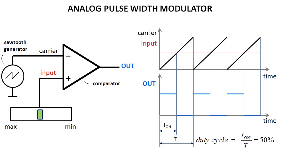
Great! So how do we produce that rectangular wave?
Well, first of all, instead of an analog PWM and an analog input voltage, we have a digital PWM and an input number, respectively. Instead of the sawtooth generator, we use a counter, which counts up, on every clock cycle, from to a maximum number, say, 7 (3 bit counter). After this maximum value is reached, the counter starts from 0. Then there is a register, called compare register, which is continuously compared with the counter value. When the counter value is reached, the microcontroller pull an output pin (called output compare) high. When the counter starts from 0, the pin is pulled down. The compare register holds the input number that represents our sample.
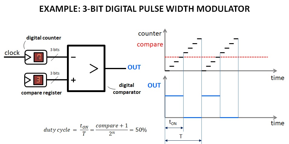
After this brief explanation, you’ll have realized that the PWM frequency (i.e. the rate at which you can update the compare register, which determines the duty cycle and therefore the average value) is simply the clock frequency of the counter divided by number of steps of the counter. In our example, we go from 0 to 7, which corresponds to 8 steps, hence the frequency is Fcounter/8.
You’ll have also realized by now that if you want to produce with a single PWM a 16-bit value, you must have a PWM frequency of Fcounter/65536. In our Arduino, Fcounter can be at most 16MHz, yielding only 244Hz, i.e. totally useless! On the other hand, if you want to go at 20kHz, you should have a Fcounter equal to 1.31 GHz! That’s insane!
However, we still have some tricks. The math!
In fact, as we can write 37 as 3*10 + 7*1, we can express a 16-bit number as the sum of two separate 8-bit numbers, each one multiplied for a “weight”. In other words, a 16-bit number N can be written as HH*256 + LL, where HH and LL are 8-bit numbers.
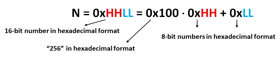
This is clearer considering the hexadecimal form: 0xnnmm = 0xnn * 0x100 + 0xmm*0x1 (0xnnmm denotes that nnmm is in hexadecimal form. 0x100 is 256 in decimal). Very simple! For instance 0x1234 = 0x12 * 0x100 + 0x34.
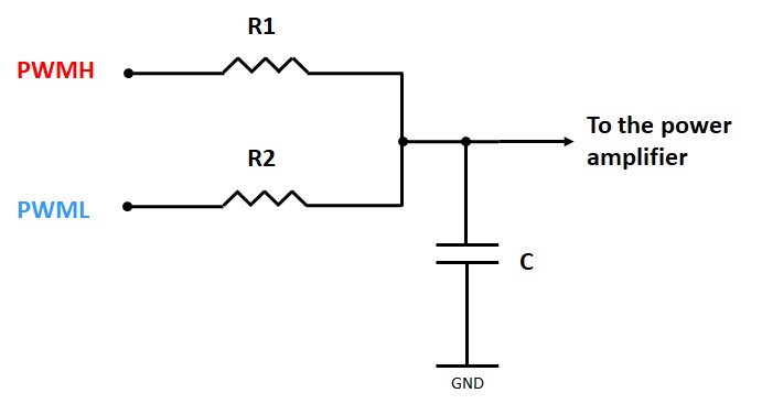
Therefore we can use two 8-bit PWMs and then sum them:
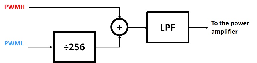
This is actually achieved using a couple of resistors! The capacitor filters out some of the PWM high frequency signals.
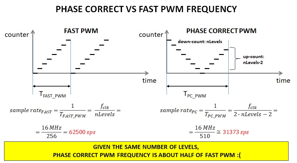
Before we continue, we must also introduce the frequency and phase correct PWM. In fact, if you have a changing compare value, you’ll end up in a square wave similar to the figure below:
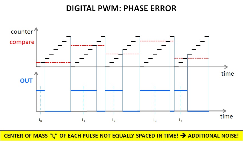
As you can see, the “center of mass” of the pulses is in position, which is not constant over every period. Although this still works, it negatively impact on the output quality.
The solution is the so called phase-correct PWM, which is obtained with an up-down counter: the counter counts up from 0 to the maximum value and then it counts down back to 0.
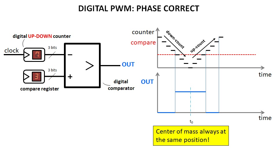
The output signal now has the center of mass of each sample always at a constant interval.
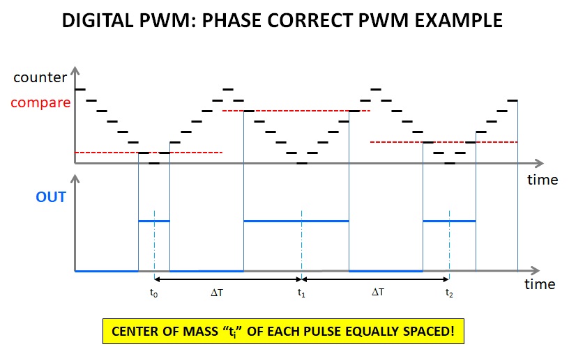
This has one major drawback: the PWM frequency is almost half, given the same clock. In fact, the cycle is now from 0 to 255 (256 steps) plus 254 to 1 (other 254 steps). This gives 510 steps. However, even if the frequency is almost halved, the quality will be better.
Back to the summation of the two PWMs, we need to choose the value of R1 and R2. The resistor (R2) connected to the PWM which will output the “0xLL” value must be 256 times smaller than the resistor connected to the PWM outputting “0xHH”. Also, to avoid distortion, this ratio should be very precise, better than 1/256, i.e. with a tolerance smaller than 0.39%. We verified that you can use 1% resistors provided that you measure them with a DMM and make sure that the ratio between their values is 1:256 with a maximum error less than 0.39%. Since many DMMs do not have enough precision (and number of digits), it’s better to use 0.1% resistors.
That said, we must find a couple of resistors, which are exactly in ratio 1:256. Well, if you calculate 1/256 you achieve 0.00390625. That is, if you take 100kOhm, you can use a 390 Ohm resistor!
However, 390 Ohm is too small. In fact, from the ATMEGA328P datasheet, you’ll find that the output resistance of the pin is between 40 and 50 Ohm. Therefore, instead of connecting 390 Ohm, you are effectively connecting 430-440 Ohm. Do not try to correct this by lowering the resistor value. In fact, the output resistance of the GPIO pin is not constant. The solution is to use much larger resistors, such as 39k and 10M.
Noise considerations
Larger resistors are much noisier, but they make the output resistance less impactful. For instance, given a signal bandwidth, the noise power generated by 10MOhm metal film resistor is 10 times larger than the noise of a 1MOhm resistor. To calculate the effective number of bits (ENOB), we use the well-known formula:
ENOB = (SINAD – 1.76)/6.02
Where:
- 6.02 is the number of decibels per each bit.
- 1.76 is the quantization error, in dB.
- SINAD is the signal (including noise+distortion) to noise+distortion ratio, expressed in dB.
Assuming no distortion and no other forms of noise, we have, with 10 MOhm, about 15 bits. This would improve to 16 bit with 1 MOhms, but you must face the problem of the GPIO output resistance, which cannot be neglected if you use 3900 Ohm, instead of 39kOhm.
Still, note that the distortion caused by the PWM is much larger than the noise of a 10MOhm resistor. Furthermore, the noise coming from the power supply might exceed as well the noise generated by the 10MOhm resistor. To reduce the effects of the latter problem, one might need to use some buffers powered with a good filtered low noise supply. However, this would increase a lot the circuit complexity only to get a minor advantage, and it won’t be covered in this post.
In any case, we strongly suggest to power the Arduino with a good quality power supply, to avoid excessive noise (we found that many laptop have a very noisy USB power supply!).
Further audio quality improvements
It might be better to sacrifice 2 to 4 bits (i.e. achieving 14 or 12 bits) and use lower duty cycle values. In some cases, despite the reduced number of bits, this would improve the audio quality. Of course the ratio of the resistors should be adjusted accordingly.
Another way to improve is to use the circuit shown in the schematics above. But we think that, at this point, using a cheap SPI DAC (remember? We won’t use the SPI port so it’s free!) could even be a much better idea.
All this is outside the scope of this post, where we simply wanted to add audio for our video!
Other considerations
The theoretical maximum sample rate of this player is about 31 ksps. This will give you the best audio quality, so feel free to try to set the sample rate to 31373 in the sketch below (don’t forget to use a 31373 sps audio file!). However, in our final application we will be forced to play the audio at only 20 kHz, due to synchronization reasons.
In other words, when we want to play a 20ksps audio, we need to use two timers. One (Timer 0) will be used as PWM, while the other (Timer 1) is used to generate a 20 kHz interrupt, required to update the compare registers of Timer 0. However this will create some additional noise, which can be seen in the example below!
Let’s consider the following 20 ksps signal:
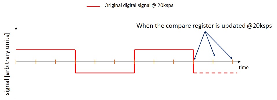
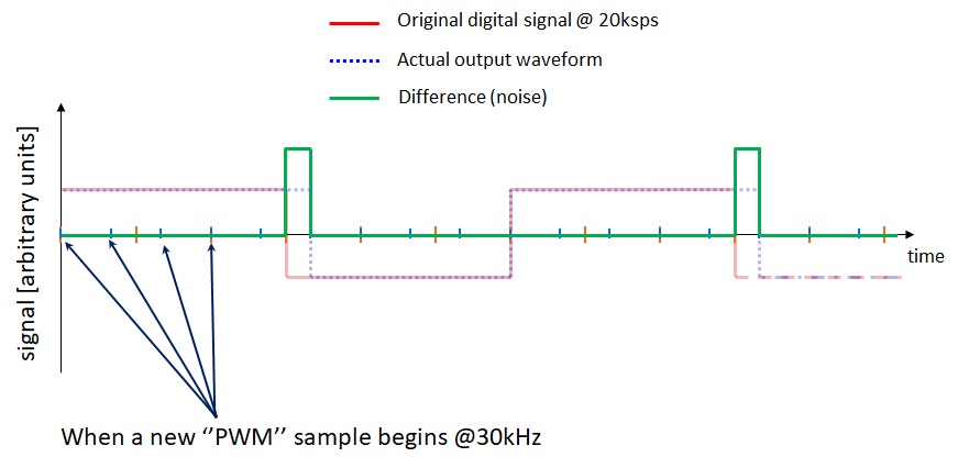
If we use Timer 0, the PWM will run at about 31kHz (30kHz in our example, for sake of simplicity!). This means that even if the PWM is running at 31kHz, we update the compare registers only at 20kHz.
The result is an error in the actual produced waveform, which can be seen below:
To avoid this, we suggest a possible modification. However it involves the use of Timer 1’s compare outputs. These pins are on PB1 and PB2, i.e. on digital pins 9 and 10, which are located in the off-grid IOH connectors, requiring a small hack if you want to create your shield using the prototyping board.
Therefore you have two possible solutions:
Solution 1:
- Just ignore the problem and use the sketch we uploaded (see below) without modifications.
This will still give a decent audio quality, but in some cases the noise, i.e. the green signal in our example, could be very noticeable.
Solution 2:
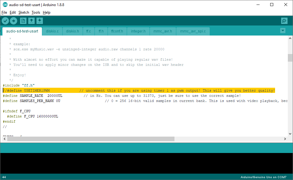
- Use timer 1, by defining in the sketch “USETIMER1PWM”.
This will give a perfect 20 ksps PWM, but you’ll need to add some wires to connect PB1 and PB2 (See in the followings). Also, you might want to adjust the volume, as we will explain later.
So, how we manage to create a 20 ksps PWM using timer 1?
Timer 1 is a 16 bit timer. Actually we won’t use all its 16 bits. In fact timer 1 is quite flexible and it allows to set the maximum counter value, by setting the register ICR1. We just have to choose a counter value that gives us the correct PWM period.

The above formula shows that 400 is the correct maximum timer value.
In this way we also save one timer, as the 20-kHz interrupt, required to refresh the compare register can be generated by Timer 1 itself!
Still, be aware that despite our sample values range from 0 to 255, the timer goes up to 400. This means that we can achieve only a maximum duty cycle of 255/400, which is about 63%. This is not a problem, we just need to adjust the value of the gain resistor in the output stage, see schematics.
Amplification?
In this post we want to produce an audio for the earpieces. A typical earpiece will deliver 15mW or less, so there is no point of having a large amplification. On the contrary, we need to attenuate our signal!
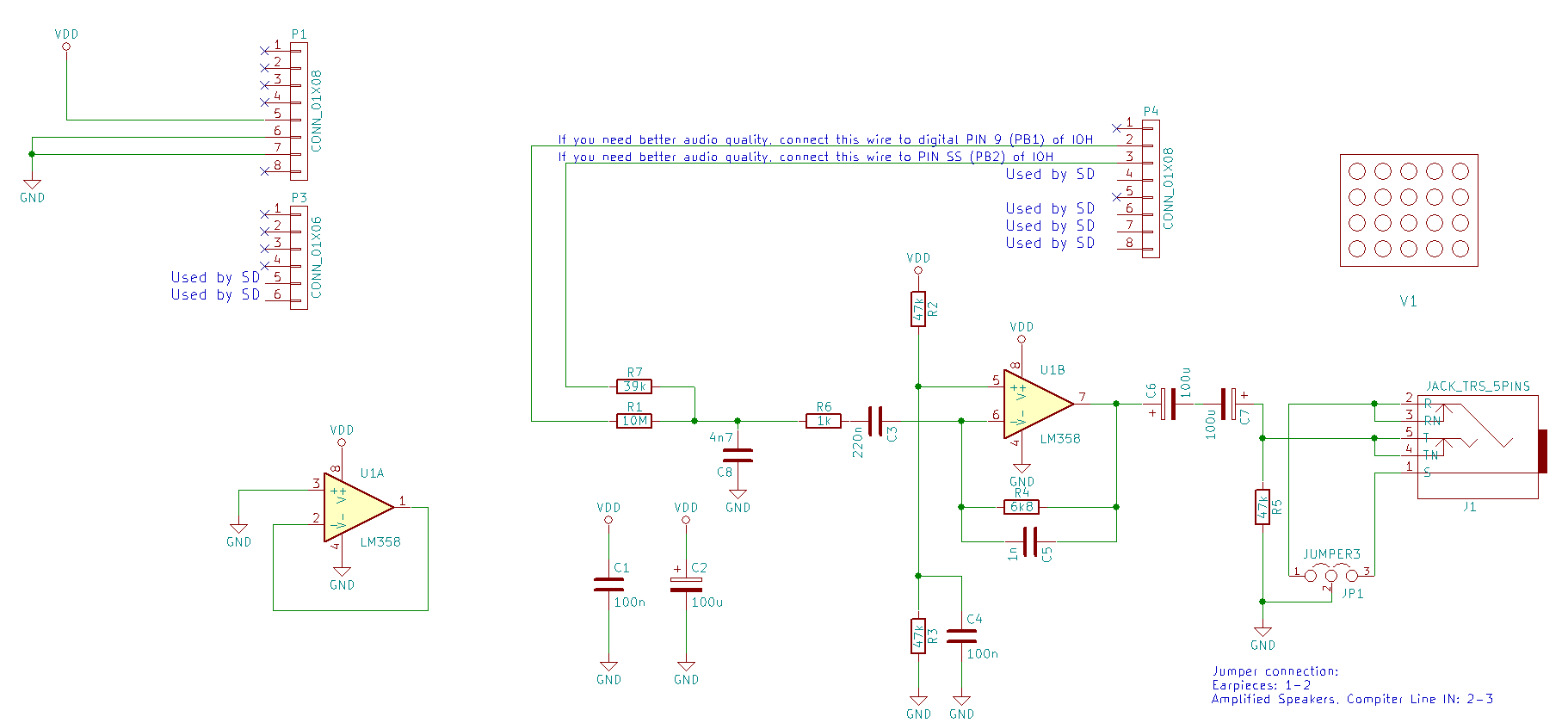
However, we still need an amplifier, to be able to drive the relatively low impedance of the earpieces. We can connect the two earpieces in series, actually doubling the impedance :). However, if you plan to connect the system to some amplified speakers, you should connect the audio to both channels and connect the center pin to ground. You can use, if you want, two jumpers, as shown in the schematics.
Hardware/software requirements
Hardware requirements:
- An Arduino Uno or compatible. Alternatively, you can use any MCU (microcontroller) of your choice. We haven’t tested this on PICs yet, but they might work as well.
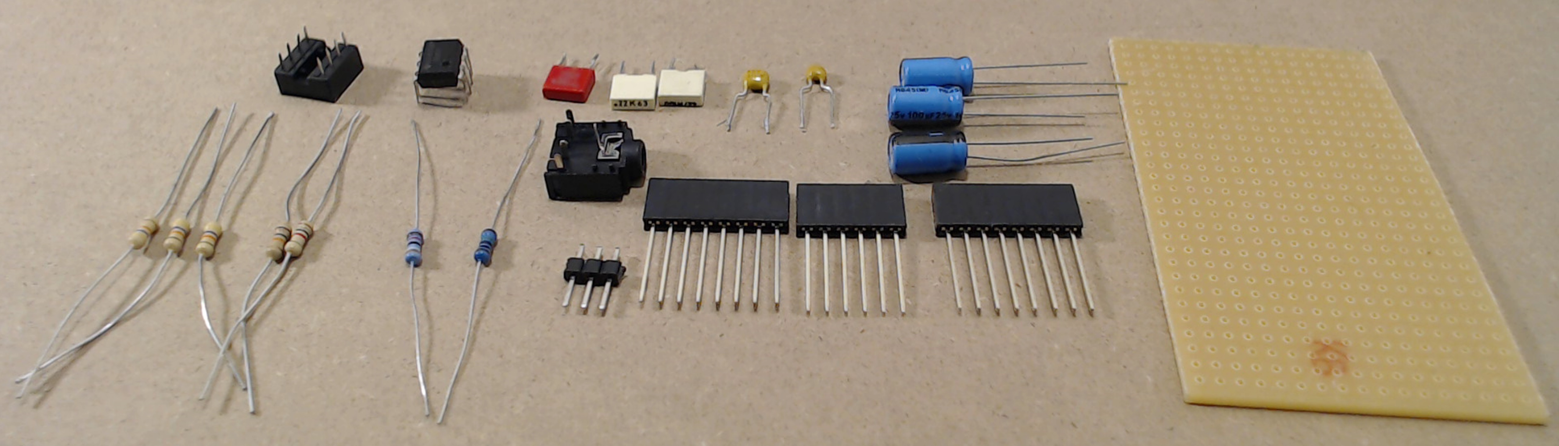
- A bunch of components (see schematics for the actual values).
- Some wires.
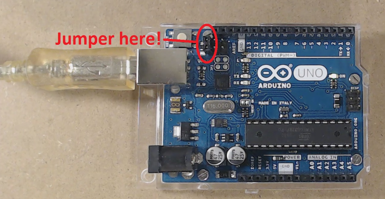
- A jumper required to keep the ATMEGA16U2 in the reset state while the audio is playing. This is mandatory!
- The Display + SD card reader board. You can also use two separate boards: one for the SD, one for the display. Note: if you use the same display we have shown you, be sure to hack it how we did in the second episode. If you just want to play audio, there is of course no need for the display.
- The shield created last time.
- A breadboard or a prototyping board (and a soldering iron). Like last time, we preferred using a prototyping board, because it yields a cleaner layout.
Software requirements:
- Arduino IDE – you can also choose the IDE you like!
- Audacity
The source code for this sketch is available here!
Let’s go for our next hack!
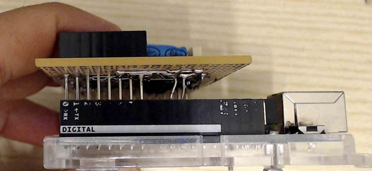
Step 1: the hardware
The schematics is shown below. Basically the two compare outputs of timer 0 (or, optionally, timer 1, see text on the schematics) are connected summed by R7 and R1 and filtered by C8. Then we use a high pass filter (C3) to block DC, and then we buffer (and filter again) the resulting signal through the OP AMP. In the schematics we show LM358, but if you are going to use a headphone, then we strongly suggest to use something with a larger output current driving capability such as TLC072, otherwise you’ll face a lot of distortion!
We used two back-to-back capacitors (C6-C7) to form a non cheap polarized-one. This allows you to directly connect the shield to almost any input, regardless their DC polarization. The jumper allows to connect either the earpiece (in this case we suggest to connect the jumper in position 1-2, so that both earpieces will be in series, so both of them produce sound) , or an amplified speaker or the line input of your PC (jumper position 2-3).
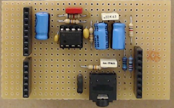
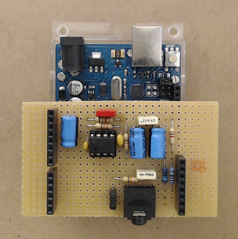
As we did in the previous post, we built a shield for the audio using a prototyping board. The layout is shown below.
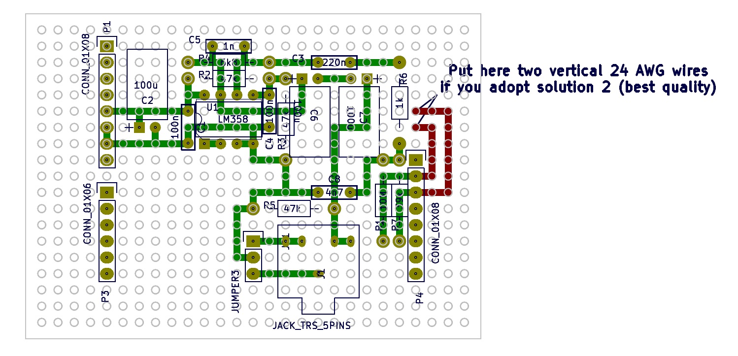
Green traces are at the bottom layer and you just need these if you want to adopt solution 1.
As written in the text note on the layout, if you want to implement the solution 2, i.e. with better audio quality, you need also to to mount a 24-AWG wire, so that it can be bent, and it will fit to the correct positions of connector IOH. Of course you also need to put the traces marked in red!
Step 2: file preparation
Use audacity to convert your favorite audio file to a 16-bit mono WAV, and select the frequency to 20kHz.
To do this:
- Install Audacity.
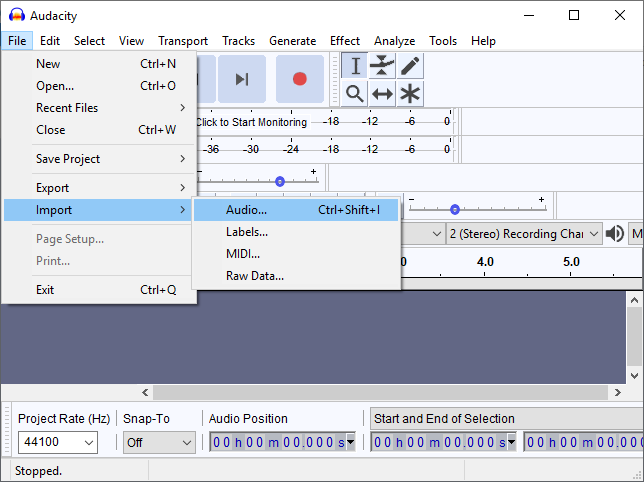
- Import the audio file you want to convert, by selecting menu File->Import->Audio
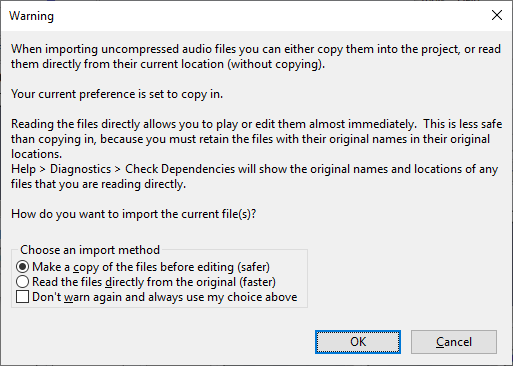
- Find your audio file press ok, and, in case this dialog appears, we suggest to choose the first option (make a copy).
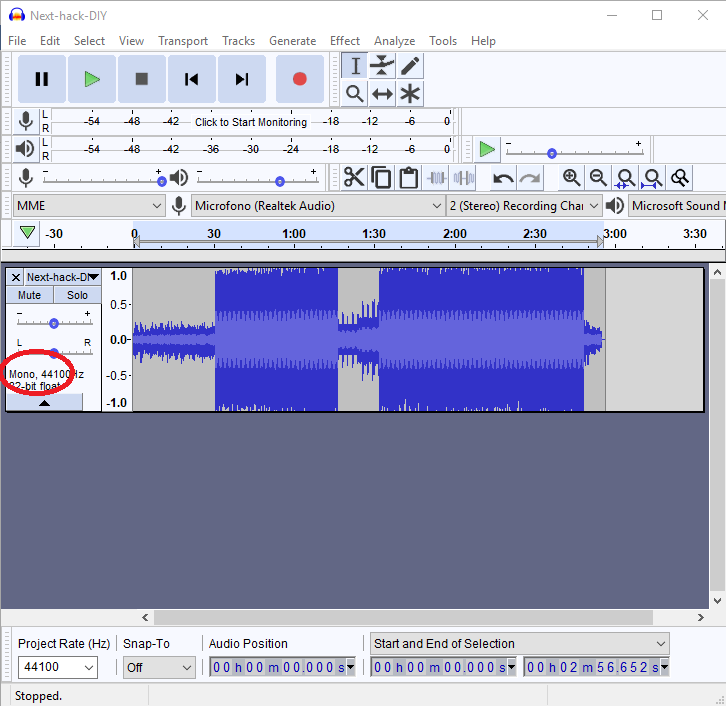
- In the case you choose a stereo audio, click on the track, and choose Track->Mix->Mix Stereo Down To Mono.
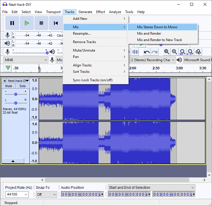
After this, the track will be shown as mono:
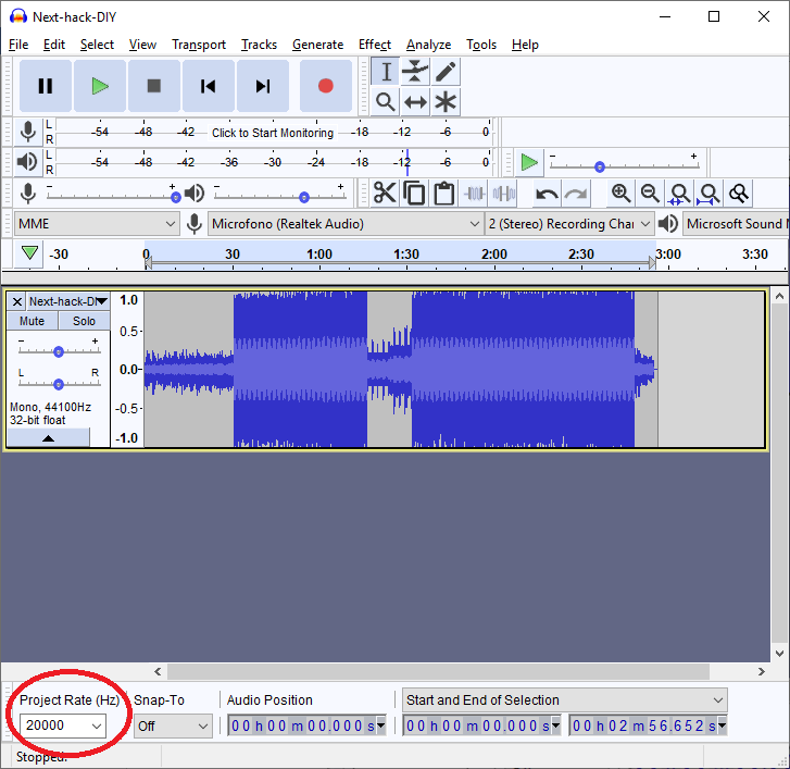
- Now, change the project rate (at the bottom) to 20000 Hz, as shown below:
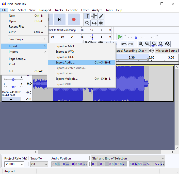
- Finally, choose menu File->Export->Export Audio
- Save the file as audio.raw. Be sure to select as: file type “other uncompressed files”, header: “RAW (header-less)” and Encoding: “signed 16-bit PCM”.
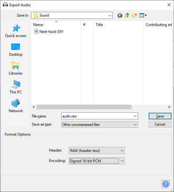
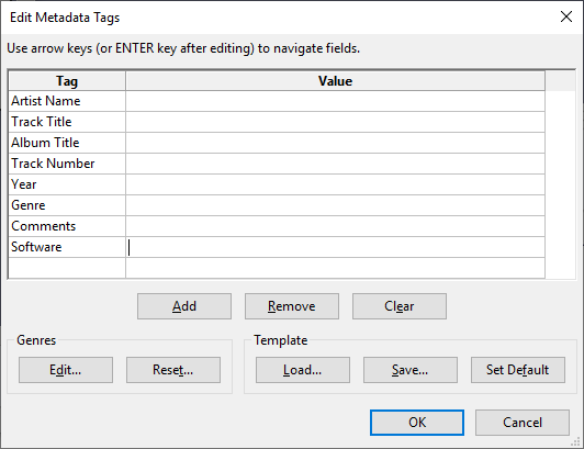
- The meta-data request will appear. Ignore it by clicking OK.
Step 3: Download the sketch program
The sketch is very simple and can be found here.
It simply sets up the PWM and instructs, via an interrupt, to set the correct compare values. The interrupt is generated using timer 1.
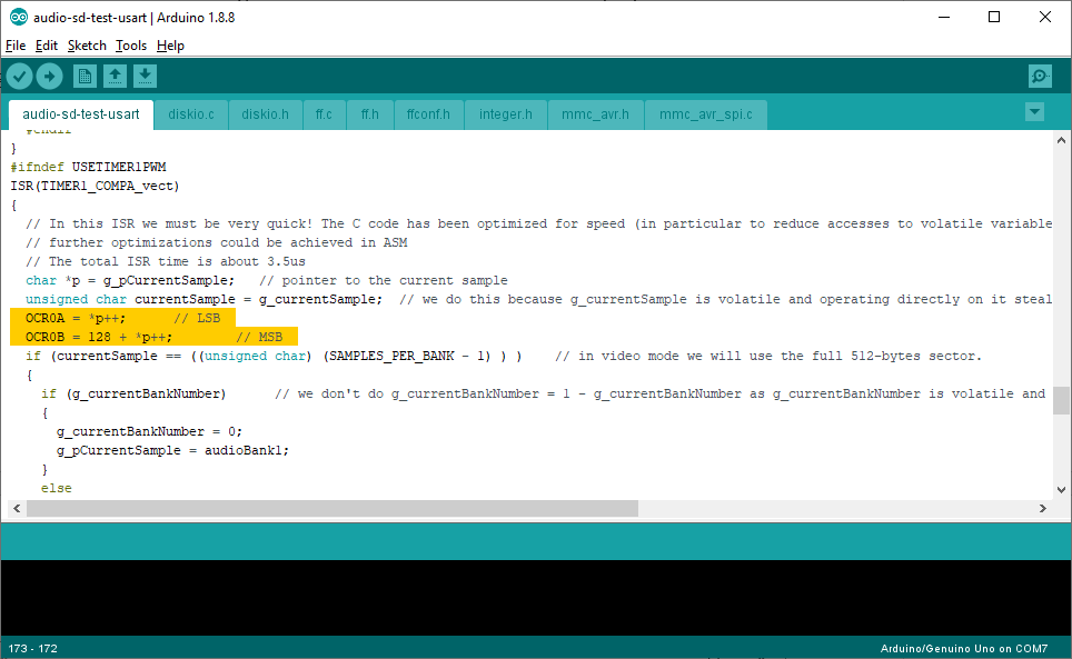
In the interrupt we put the least significant byte of our sample to one compare register, and the most significant byte to the other compare register. Actually, to the latter we add “128”, as we need a 16-bit unsigned signal (i.e. a number ranging from 0 to 65535), whereas the sample format is 16-bit signed (i.e. a number ranging from -32768 to 32767). To do this, we need to add 32768, that is just 128 to the most significant byte, and 0 to the other :).
The system use 2 512-byte bank to implement a double buffering: while we are reading one bank, we will output the samples of the other bank. In this way, we can achieve a smooth continuous playback without too much effort.
Uncomment the highlighted line, if you want to use the solution 2, which will allow for better audio!
Step 4: Program the Arduino
This is like the previous post. The jumper (as well as the shields) must be removed before programming! Remember to put back the jumper after you finished programming, to avoid contentionon the USART lines !
Step 5: Enjoy!
- Remove the power
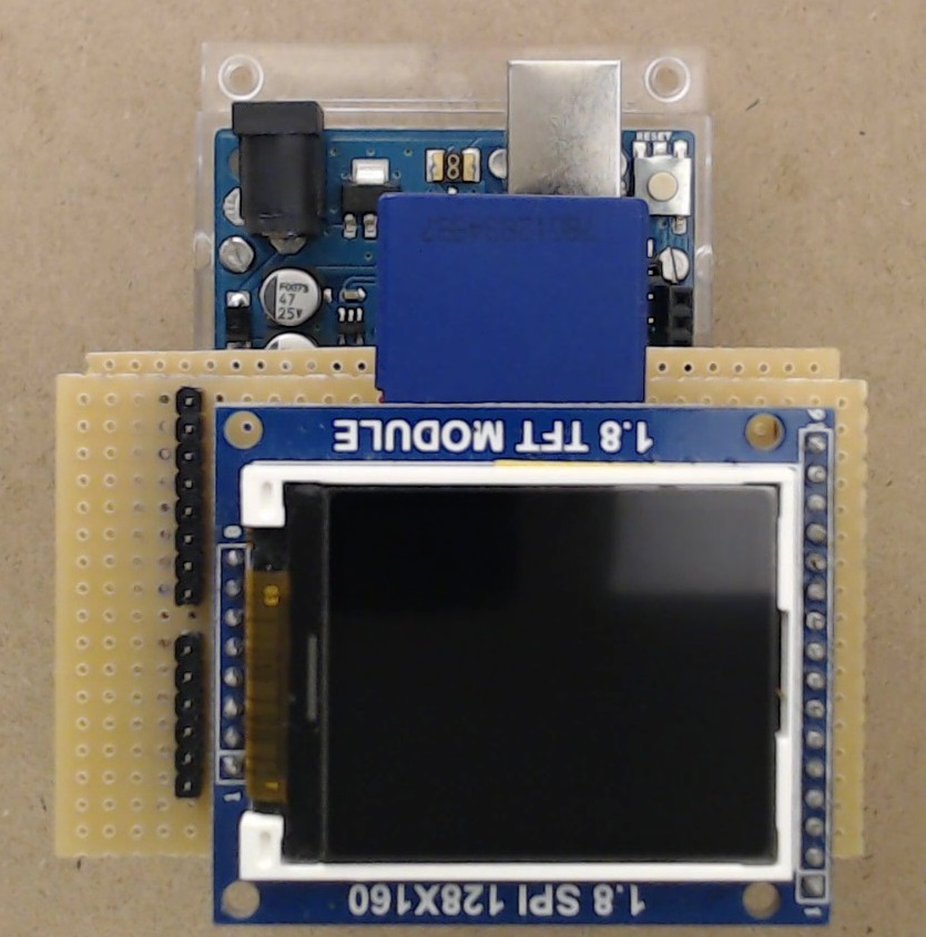
- Put the new shield (pay attention for the two wires if you used solution 2!
- Put the display shield on top of it, with the SD card already inserted.
- Insert your headphone or amplified speakers jack
Power your Arduino
You should hear your audio!
Of course the display will stay black. Nothing prevents you to improve this sketch and drive the display, to show some fancy things or a file selector.
Possible improvements!
It’s very straightforward to modify the sketch to accept directly WAV files! We leave it as exercise :).
excellent instructable series i ever seen.my salute for big effort of you have done. but one minor problem at uploading arduino codes. ff.h file is missing please upload it thanks in advance
Thank you very much! We checked the file https://next-hack.com/wp-content/uploads/2019/02/audio-sd-test-usart-1.zip and we found that the ff.h file is in the archive. We also re compiled it and everything is fine. Can you provide more information about your issue?
THESE ERROR MESSAGE IS COMING HERE…..
Arduino: 1.8.12 (Windows 7), Board: “Arduino Uno”
C:\Users\intel\AppData\Local\Temp\ccLw66Ym.ltrans0.ltrans.o: In function `deselect’:
sketch/mmc_avr_usart_spi.c:208: undefined reference to `xchg_spi’
C:\Users\intel\AppData\Local\Temp\ccLw66Ym.ltrans0.ltrans.o: In function `select’:
sketch/mmc_avr_usart_spi.c:221: undefined reference to `xchg_spi’
C:\Users\intel\AppData\Local\Temp\ccLw66Ym.ltrans0.ltrans.o: In function `wait_ready’:
sketch/mmc_avr_usart_spi.c:190: undefined reference to `xchg_spi’
C:\Users\intel\AppData\Local\Temp\ccLw66Ym.ltrans0.ltrans.o: In function `send_cmd’:
sketch/mmc_avr_usart_spi.c:315: undefined reference to `xchg_spi’
sketch/mmc_avr_usart_spi.c:316: undefined reference to `xchg_spi’
C:\Users\intel\AppData\Local\Temp\ccLw66Ym.ltrans0.ltrans.o:sketch/mmc_avr_usart_spi.c:317: more undefined references to `xchg_spi’ follow
collect2.exe: error: ld returned 1 exit status
exit status 1
Error compiling for board Arduino Uno.
This report would have more information with
“Show verbose output during compilation”
option enabled in File -> Preferences.
The problem was caused to the new GCC included with Arduino 1.8.12 (with 1.8.8 it worked fine), which are more strict. To solve this problem, add in line 119 (of mmc_avr_usart_spi.c) the keyword “static” (without quotes). It should read: “static inline” (without quotes).
We are uploading the correct archive now.
I CAN UPLOAD BLINK PROGRAME WITH NO PROBEM BUT THIS CODE SAYS
exit status 1
Error compiling for board Arduino Uno.
Hi! See the previous comment!
waiting for final part release 🙂
Me too