
Introduction
Hi there!
This is the second step of our “How to play a video on Arduino” tutorial!
For video playback we will need high transfer rates. High transfer rates are also required or desired in many other applications, so this hack might be useful even if you are not going to play a video! The Arduino’s SPI can reach a clock speed of 8MHz. However, such a high speed is not supported by many shields or add-on cards.
In this hack episode we will show you how to modify the popular 1.8” TFT module with SD card, to enable high speed read/write transfers.
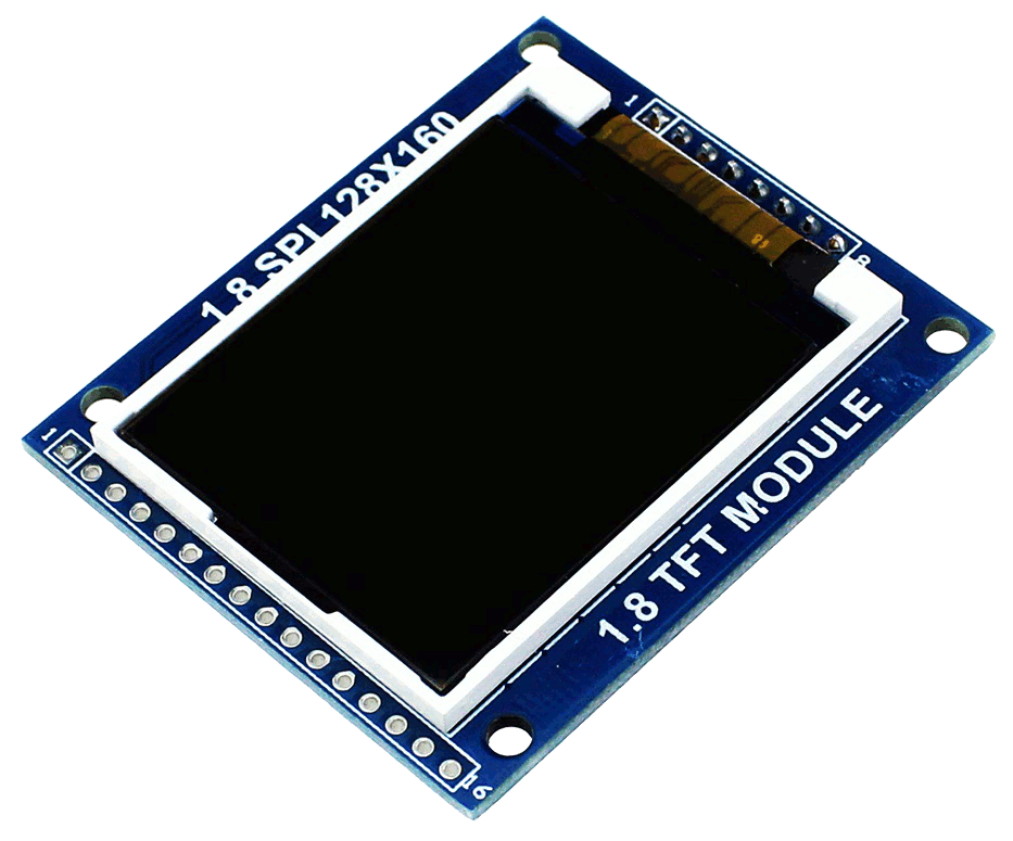
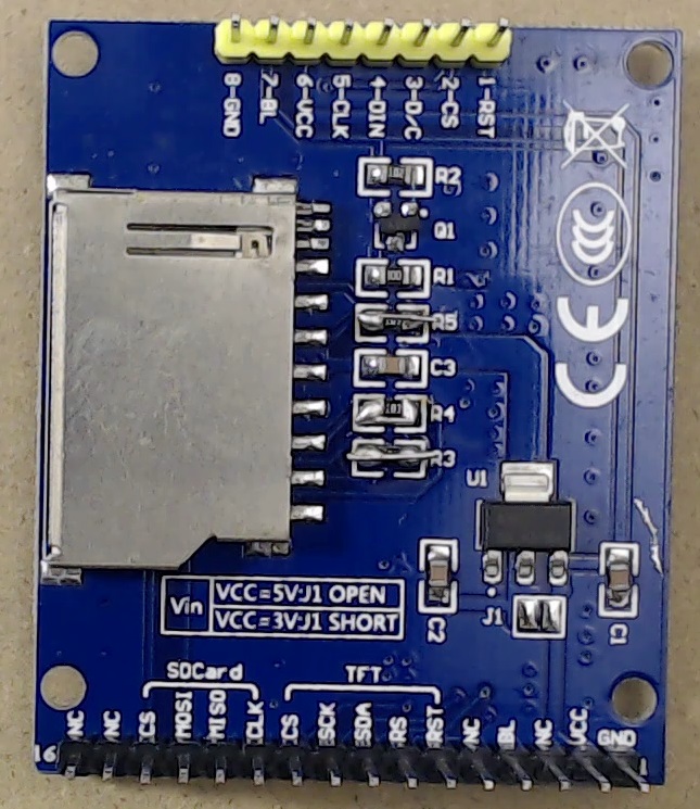
This module is very cheap, and it also features an SD socket, which is handy, because we are going to store our video on the SD card. The SD signals are routed on the left, and you can directly connect them to an Arduino. However, you’ll find that you cannot use a clock frequency higher than 1MHz.
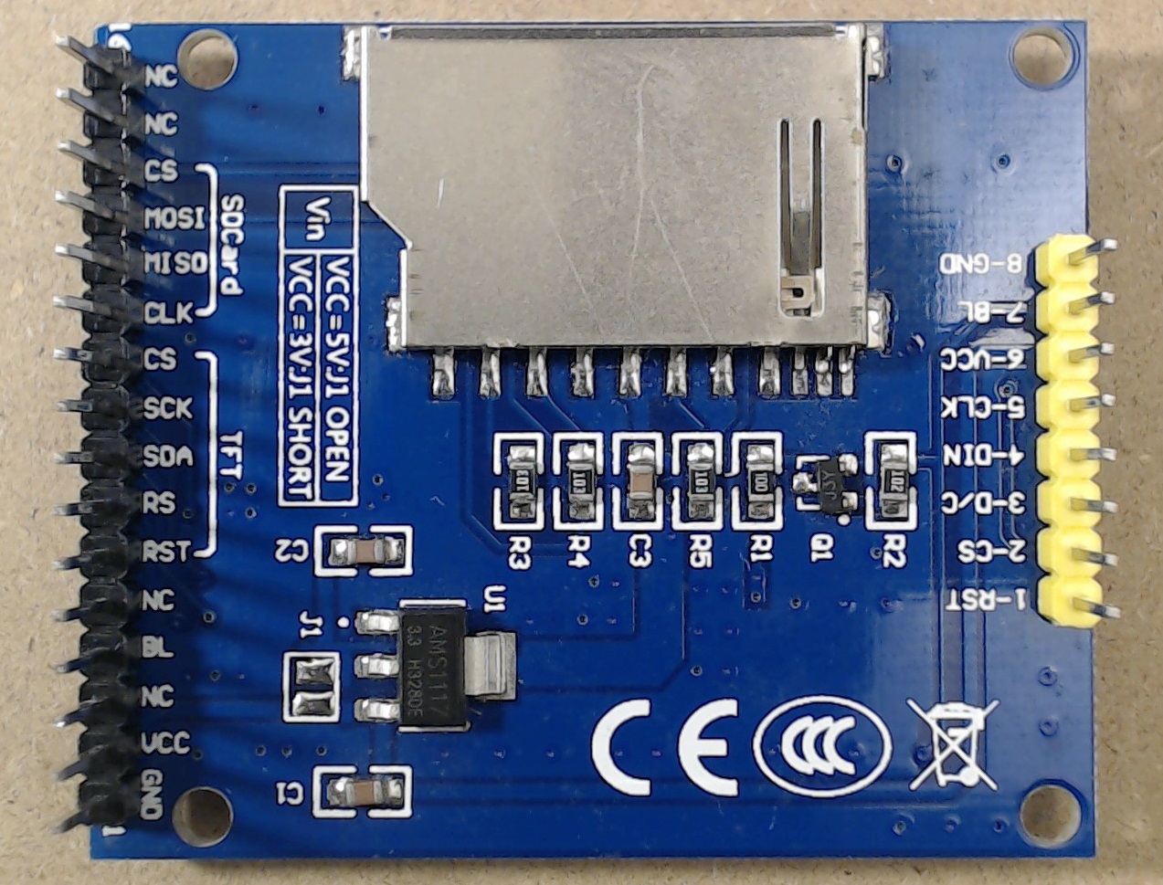
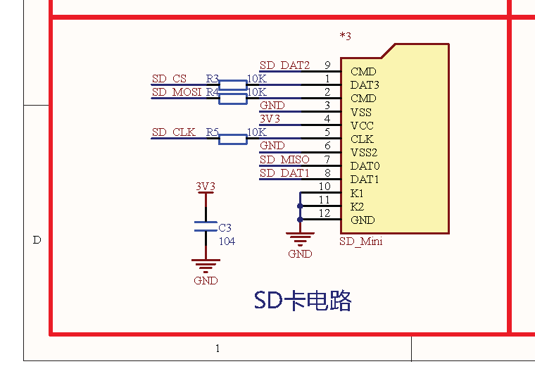
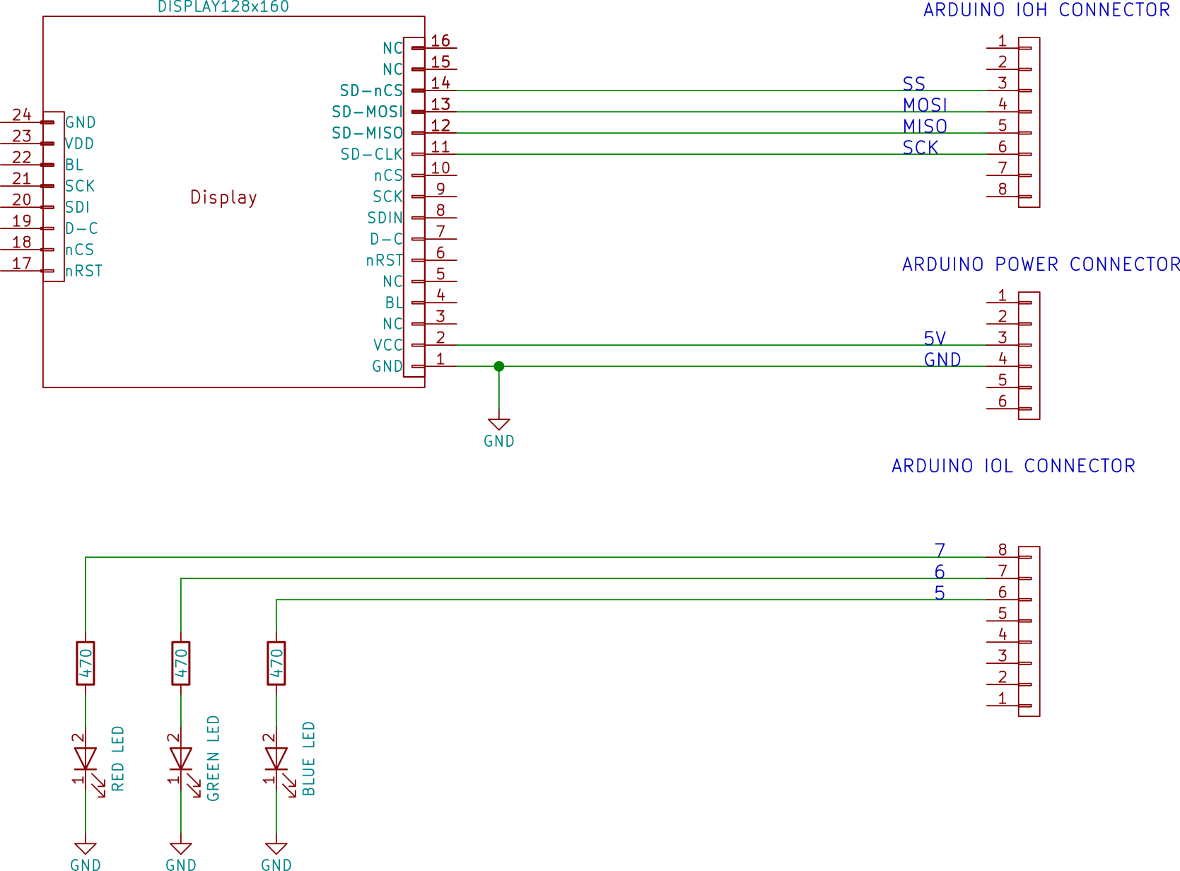
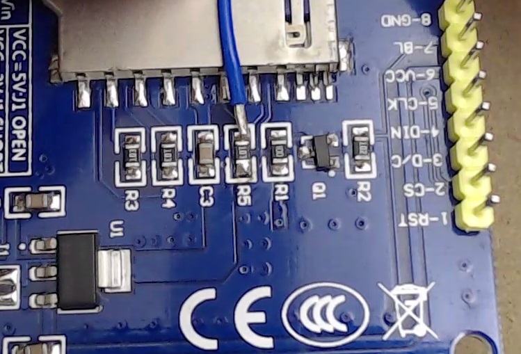
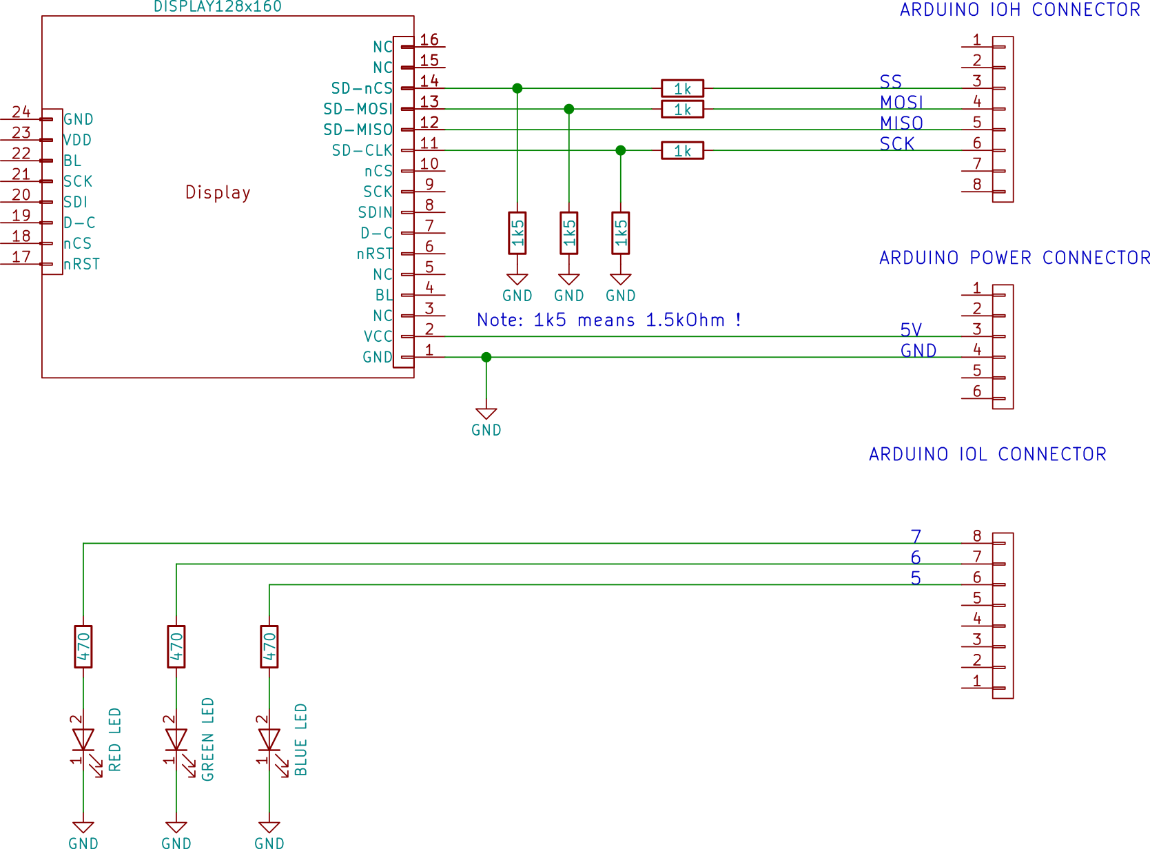
This is due to the 10-kOhm resistors (R3 through R5) that are in series to SD_CLK, SD_MOSI, SD_CS, to protect the SD Card when you connect the module directly to a 5-V system, such as the Arduino Uno. (see the schematics below. You can find the full schematics QDtech_1.8). These resistors make a low-pass filter together with the parasitic stray and SD capacitance.
The solution is to short the 10-kOhm resistors or, at least, change their values to 330 Ohm or less. Although it might still work, we do not recommend using higher values than 330 Ohms, as the signal could be too much degraded.
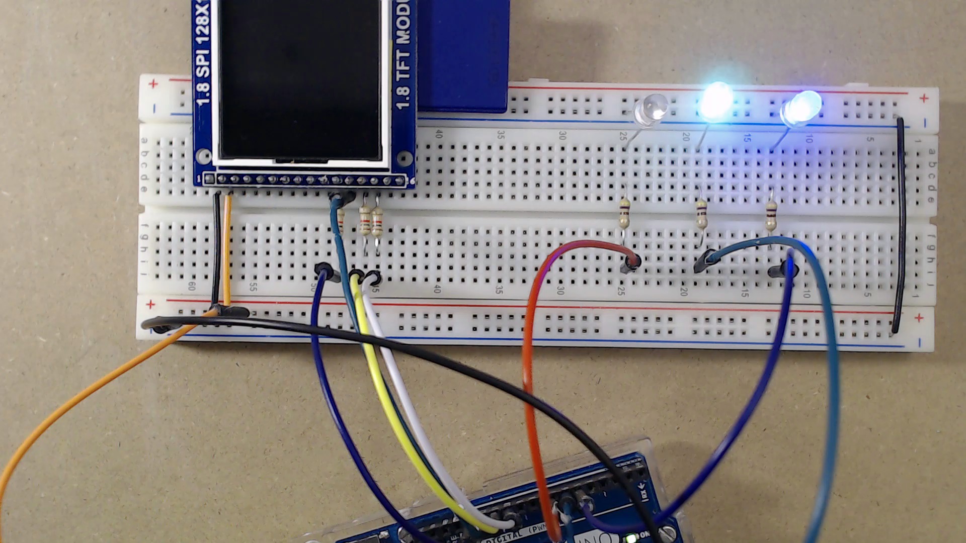
To test our system we created a simple sketch using the Arduino IDE (you can find the complete source in the links below). We used the FAT Fs of ELM-ChaN ( http://elm-chan.org/fsw/ff/00index_e.html ), which we adapted for Arduino. The test program performs a read test at 500 kHz, and a read test at 8MHz. The red LED stays on for the whole duration of the tests, and it is turned off once the read operations have been successfully completed. The green LED flashes during transfers, and stays on if the program ended successfully. The blue LED indicates if we are running at high speed (LED on) or low speed (LED off). The program advances to the high-speed phase only if the low-speed phase completes successfully.
The following images show the connections required for the test program. Important! Do not use this connection after you modified the display module!
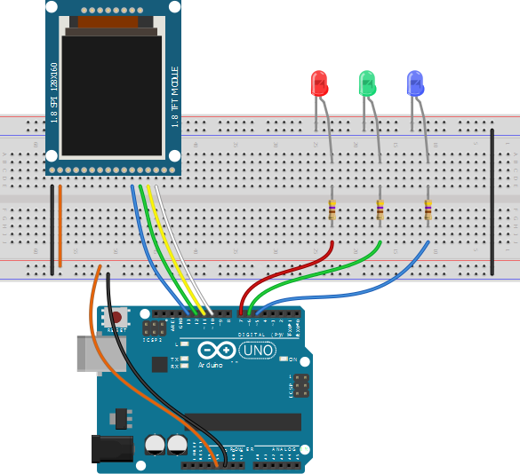
The breadboard image was created with Fritzing (http://fritzing.org).
As you can see, at 500kHz the SD card works (the blue LED is on, indicating that the system is testing the SD card in high-speed mode, as the low-speed test was successful).
However, at 8MHz it doesn’t. Playing with the frequency settings we found that at 1MHz works too (depending on the card, even at 1MHz it might not work). At 2 MHz, it doesn’t.
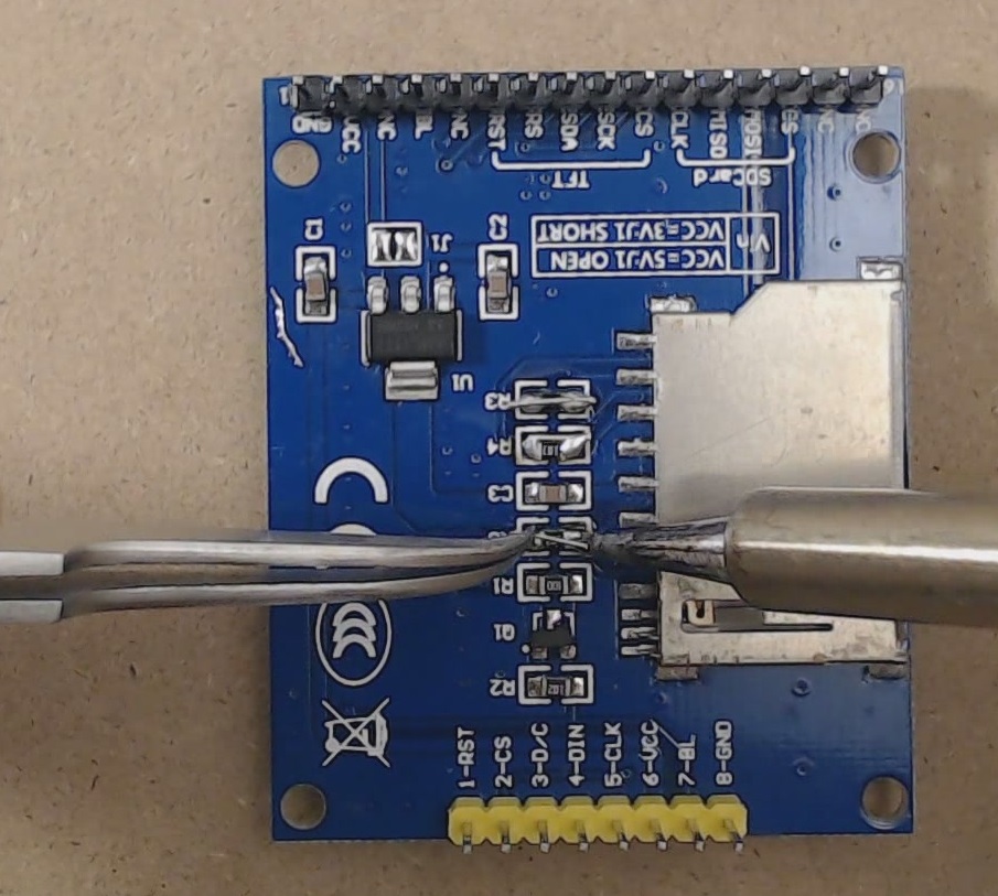
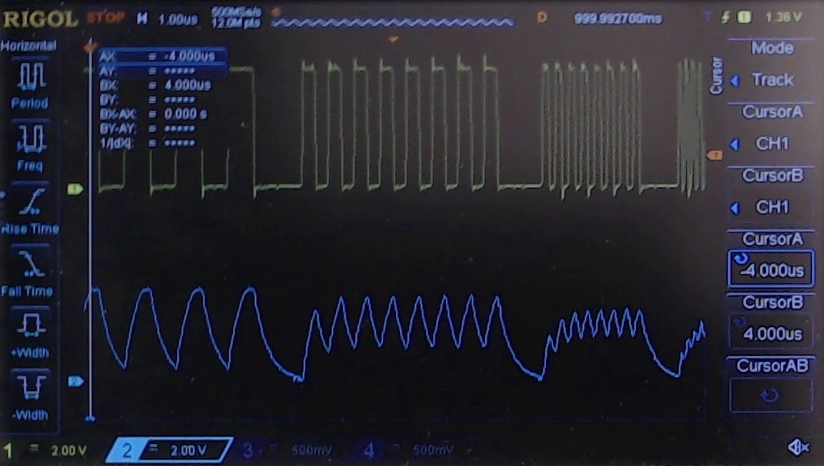
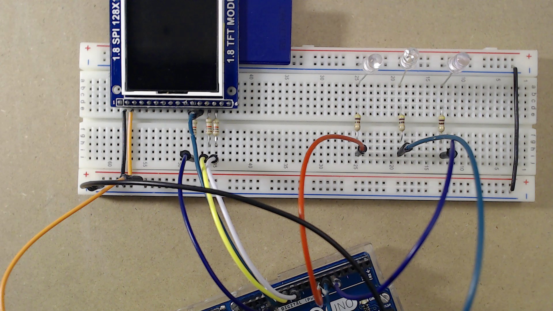
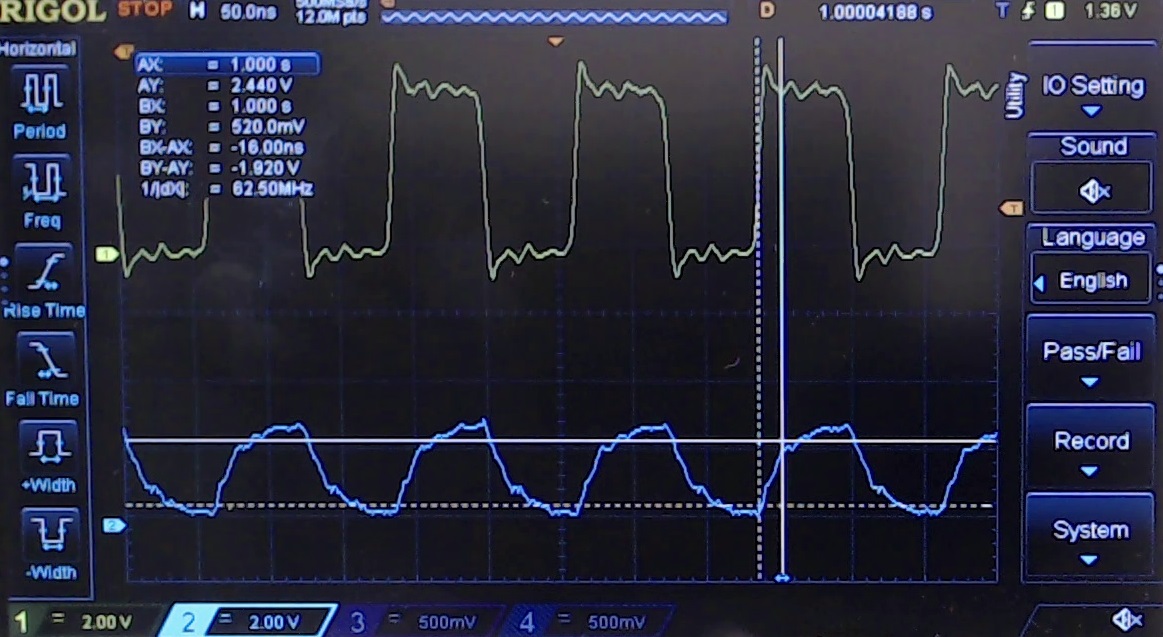
To better appreciate how the signal is degraded at the various speed, we soldered a wire close to the SD clock input (see image below) and we hooked it up to the oscilloscope. We also wrote a simple program (download sd-test) that outputs one character (0xFF) to the SPI at different clock frequencies. At 1MHz the signal is already very degraded, and it’s a miracle if the card still works. At 2MHz we aren’t surprised that the SD does not work.
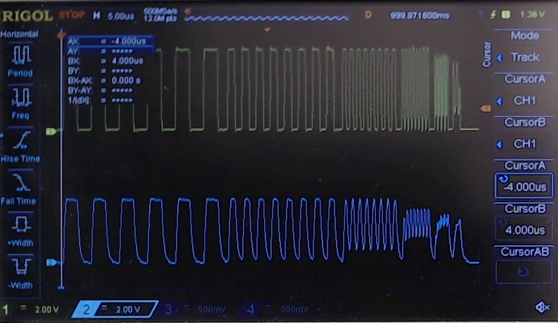
(please note that even though due to the resolution of the scope screen, it seems that the CPU creates a bad square wave at high frequencies, it actually does not: the square wave is good even at 8MHz).
So, let’s modify the module and check if the hack works!
Requirements for this Hack
Hardware required
- An 1.8” TFT display + SD board or equivalent.
- Some wire (or some 0805 0-Ohm to 330-Ohm resistors).
- A soldering iron.
- Soldering wire.
- A 16-pin straight male header (required only if you haven’t it soldered already)
- 3x 1-kOhm resistors (for 5 to 3.3V converter).
- 3x 1.5-kOhm resistors (for 5 to 3.3V converter).
- Breadboard (to test the hack).
- 9x jumper wires (to test the hack).
- Arduino Uno or similar (to test the hack).
- An SD-Card (to test the hack).
- An SD card reader on your computer (to program the test file).
- One red, one green and one blue LED, with 3x 330 Ohm resistors (to test the hack).
Software required (only if you need to test this hack)
- Arduino IDE (or other C/C++ programming environment of your choice)
- This zip containing the sketch and the modified ELM Chan’s FatFS for Arduino. If you wish to learn more about ChaN’s FatFS, visit his website: http://elm-chan.org/fsw/ff/00index_e.html .
Procedure
Step 1:
In case your SD+display module does not come with the 16-pin strip line, get one and solder it!
Step 2:
IMPORTANT! AFTER THIS MODIFICATION YOU’LL NEED SOME SORT OF 5V to 3.3V CONVERSION (e.g. a resistor divider, see below!) OTHERWISE YOU MIGHT DESTROY YOUR CARD/ARDUINO.
As said before, you just simply need to change those 10-k Ohm resistors, with anything like:
– A wire.
– A 0-Ohm to 330 Ohm resistor (i.e. 100 Ohm would be fine too).
In this example we just shorted out all the 10-kOhm resistors.
Step 3:
Once again, remember that, if you want to use the SD Card on a 5-V system, you will have to put some sort of 5 to 3.3V conversion in the system! A very easy way is to use a resistor divider: get a 1-k and one 1.5-k resistors, and connect them as shown in the schematics. This will lower the 5V to 3V, preventing any damage to the SD Card, while maintaining the full speed capability.
For instance, you can prepare the breadboard like the picture below.
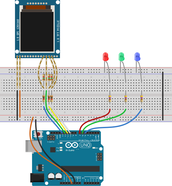
The breadboard image was created with Fritzing (http://fritzing.org).
Please note that the breadboard drawings shows the display module wired. We did this to show where the 1.5kOhm resistors are placed. However, in practice, we will put the display as shown in the picture below: remember that there are some resistors under it. Do not push too hard, as you might short out the resistors!
Step 4:
Install the latest Arduino IDE (if you haven’t it yet) and download this zip sd-test, containing the test program.
Step 5:
Unzip the file in a place of your choice, and open the “SD-test.ino” sketch.
Step 6:
Program your arduino. The file contained in the ZIP is already set up for the maximum speed.
Step 7:
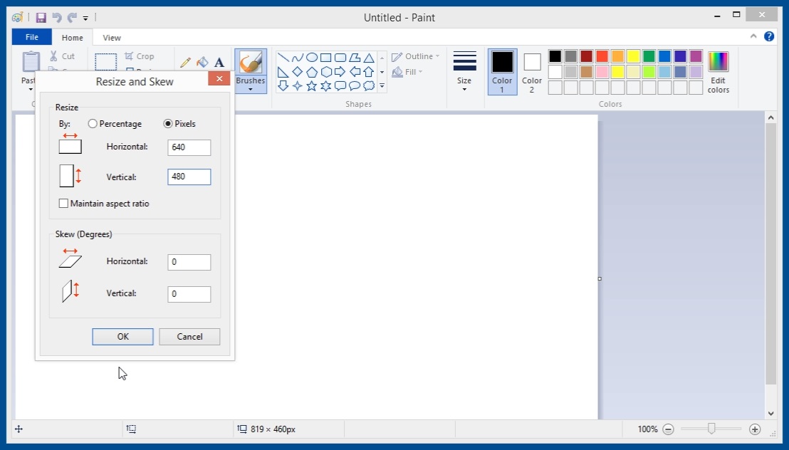
Create a bmp file with about 1MB in size (do not exceed with the size, otherwise the low-speed test will take forever!), and name it “test.bmp”. For instance, with a paint program create an empty 640×480 24-bit bitmap and save it on the SD with the name “test.bmp”. This should create a 900-kB file. (warning: of course nothing will be displayed, as the display is not connected and we did not put the code for it!)
Step 8:
Insert the SD card in the slot and power up the arduino.
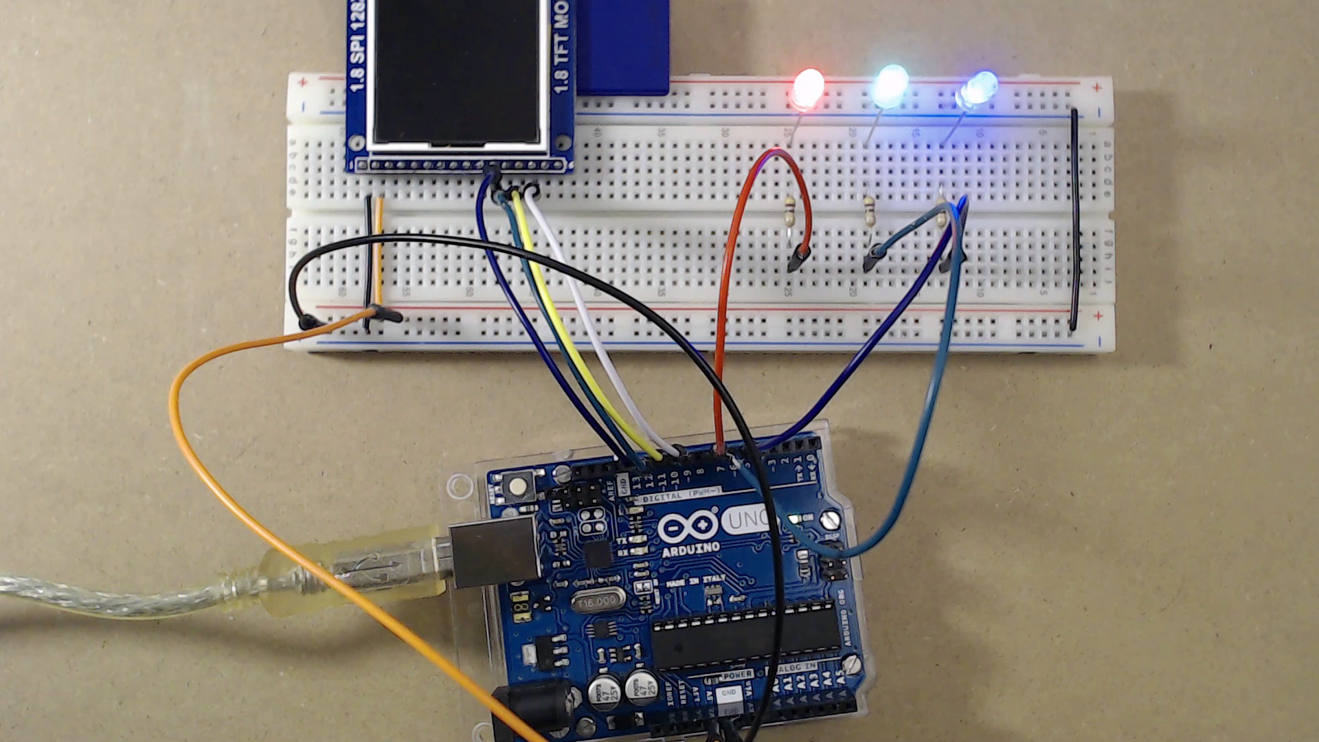
If all is ok, the green LED should flash for a while, then after about 15 seconds the blue led should turn on.
After that, the green LED should flash much faster, and in few seconds both the green and blue led should stay on, and the red LED should turn off.
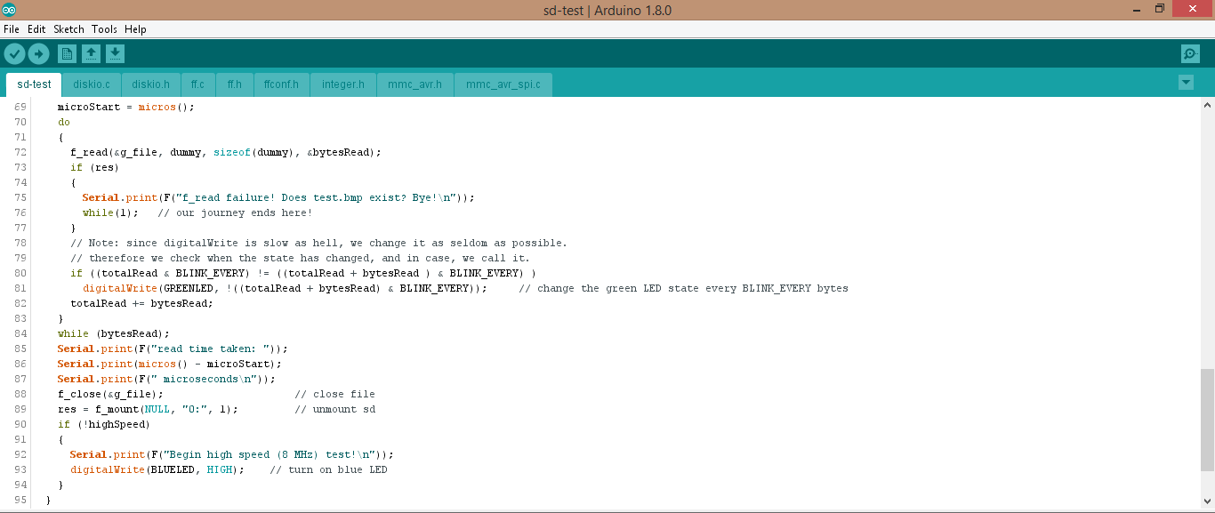
Here’s the monitor output!
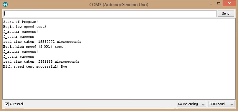
Finally, in the scope you can notice that now the clock signal is acceptable even at 8MHz! The green LED ON (with the red LED OFF) indicates that the SD mount and file read operations were successful even at high speed.
Watch the videos on our youtube channel next-hack! Subscribe to get all the updates and share with your friends!
Direct link to the video of this episode available here.
In the next week we will show you how to improve even more the read speed! Stay tuned!
can you just do this SD card hack to get faster transfer of bitmaps.If so I assume you still need the sketch in this article to draw the bitmap on the tft?
I use LEDs as a simple 5V to 3V3 converters – mostly those yellow/green ones.
Nice trick indeed! In series (so that 5V drops to 3V), with a pull down resistor, right ?
Sure, the 1K pull-down is requisite if you want to see the LED glowing and also is a must from the functional point of view, considering the one-way nature of a LED.